Kalman
-
Posts
15 -
Joined
-
Last visited


Kalman's Achievements
")


-
clevo We did it. TM1 heatsink has been grafted to KM1
Kalman replied to KabyZen's topic in Sager & Clevo
I have a DM2 and currently working on to fit the TM1 CPU cooler. The frame must be cut to fit the extra radiator above the VRM. And the hardest part is the mounting screws are 4mm lower on the TM1 than the Dm2 CPU cooler.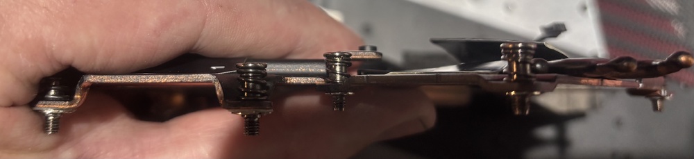
-
GeForce RTX 4090M installed in HP Zbook 17 G5
Kalman replied to ichime's topic in Components & Upgrades
Hi, It is very promising for future improvements! I have not seen anyone use MXM RTX 40 series in any other laptop. Is it the first of a kind? -
Hi All, I have a Tornado F5, originally it was shipped with a 1070. Unfortunately that card bricked and I swapped for a 980. Now I wonder to change it to 1080 but the official website says: “In order for you to use the GTX 1080 you must have the motherboard that supports the GTX 1080. If you purchased your notebook before this model was capable of using the GTX 1080 your motherboard will not support it! The upgrade to make your motherboard capable of using the GTX 1080 is available below listed under Services.” Someone knows what this is? Is it a bios upgrade or something else?
-
Could the mxm port support 150W?
-
I have a GTX1080 from Clevo P870DM2. I just upgraded to RTX3080. No pads, no power cable just the card. €180
-
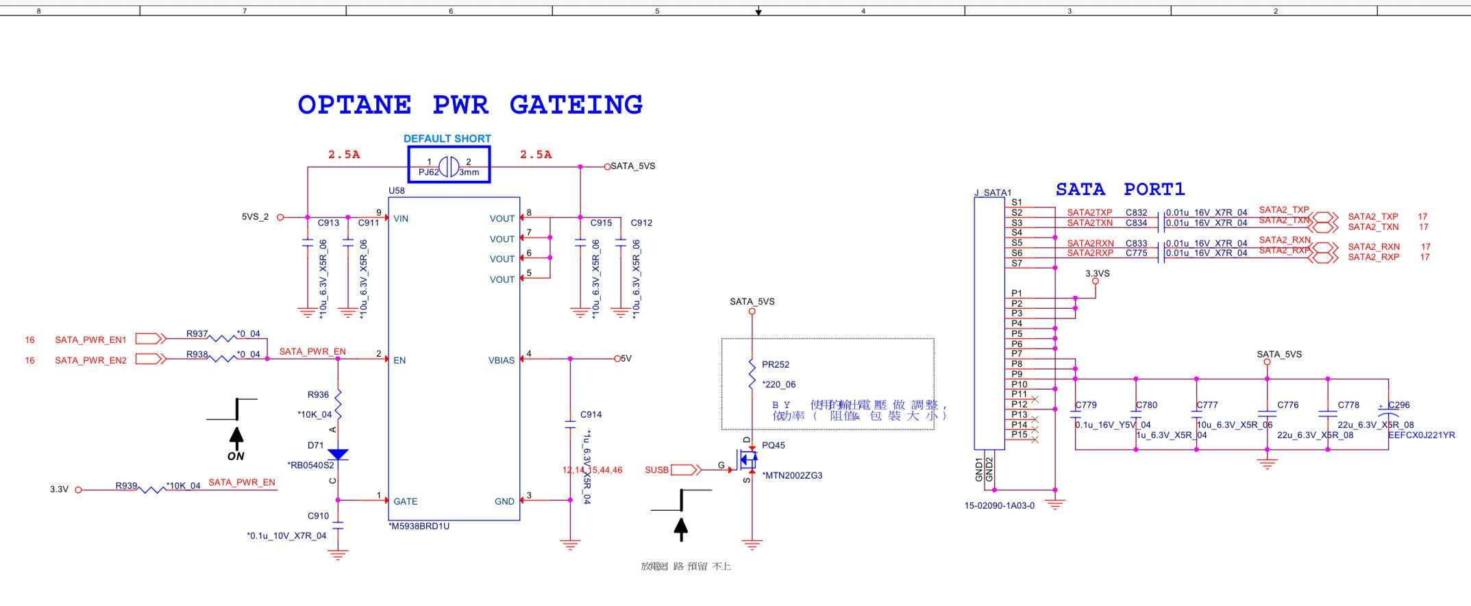
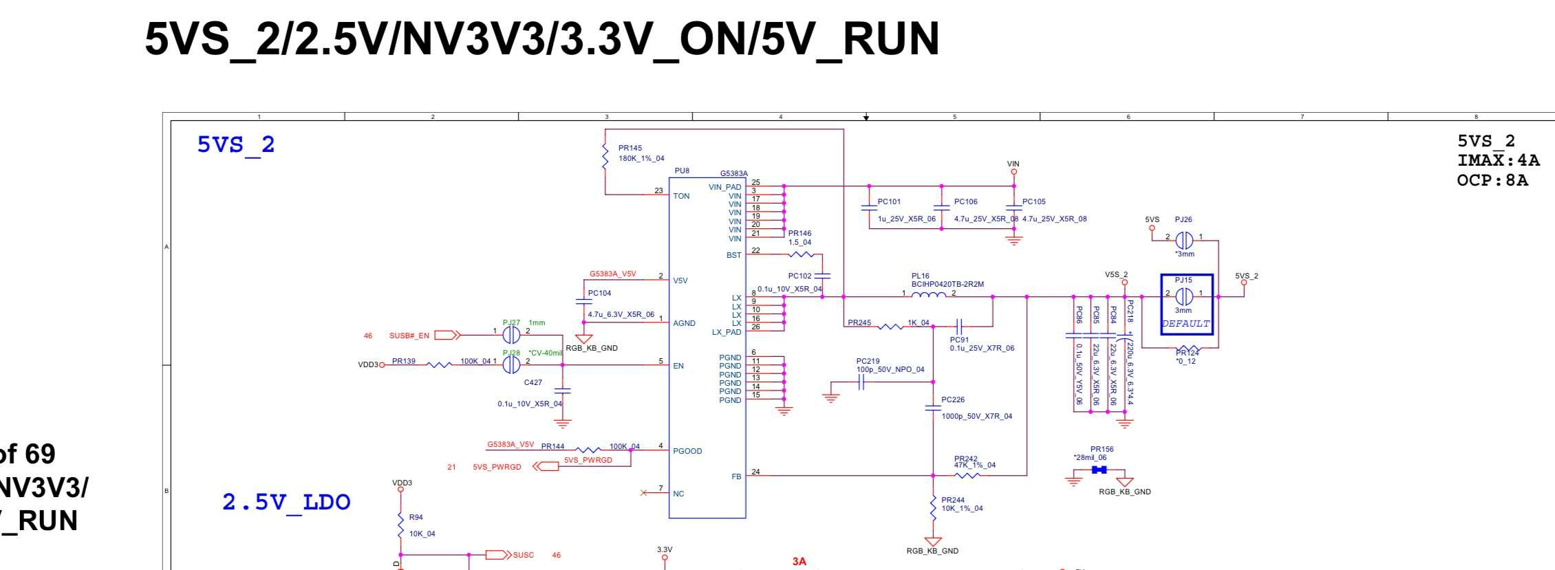
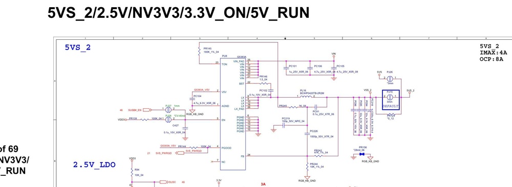
Hi, I do not know much about these adapters nor AMOLED panels. But I think the most important question is how much current is needed for these panels to work? The most current you can get based on the SM of the P775 is the SATA 5V power. The 5VS is limited to 2.5A which is maybe sufficient for the AMOLED. But you can not use any more HDD. The PU8 is producing the 5V for the SATA, in the top right corner 4A is for the whole circuit branch you can not use all of it. U58 MOSFET is a load switch for the SATA power but I think it is not in use default because PJ62 jumper is short on default. You can see the power limit is 2.5A. SATA_PWR_EN is default ON which means if it is in use you should have 5V on power on. Conclusion is if you panel is not using more then 2.5A then you can use SATA 5V but you can not use HDD simultaneously. Perhaps you can use an USB-C to SATA power cable, but I think it is very important to use a fuse(2.5A). If someone with more experience with these adapters and AMOLED panels could help would be nice. This is just my theory how these circuit work it can be incorrect!

-
Thank you for the response. I was monitoring the temp the whole time also there is thermal control. There is no big difference between vertical and horizontal position.
-
Hi, In this Video which is a very good one by the way I think, explains the mods/mats if you interested. Perhaps you could measure the memory rail voltage at the inductor, it should be around 1.2 volt. All of your memory banks are failing. I think you are right about the memory controller is in the GPU if it fails its over. If you have a local shop somewhere maybe they could try reballing the GPU..it might help. I do not think it would help. You definitely should get one! There is no better time then now..:)

- 16 replies
-
- 2
-

-
- p775dm3
- gtx 1080 mxm
- (and 1 more)
-
Thank you! Yes, that is a good idea! I did the first test in a vertical position. I will do it again vertical and horizontal.
-
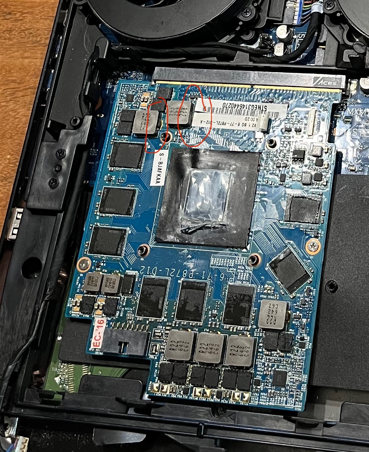
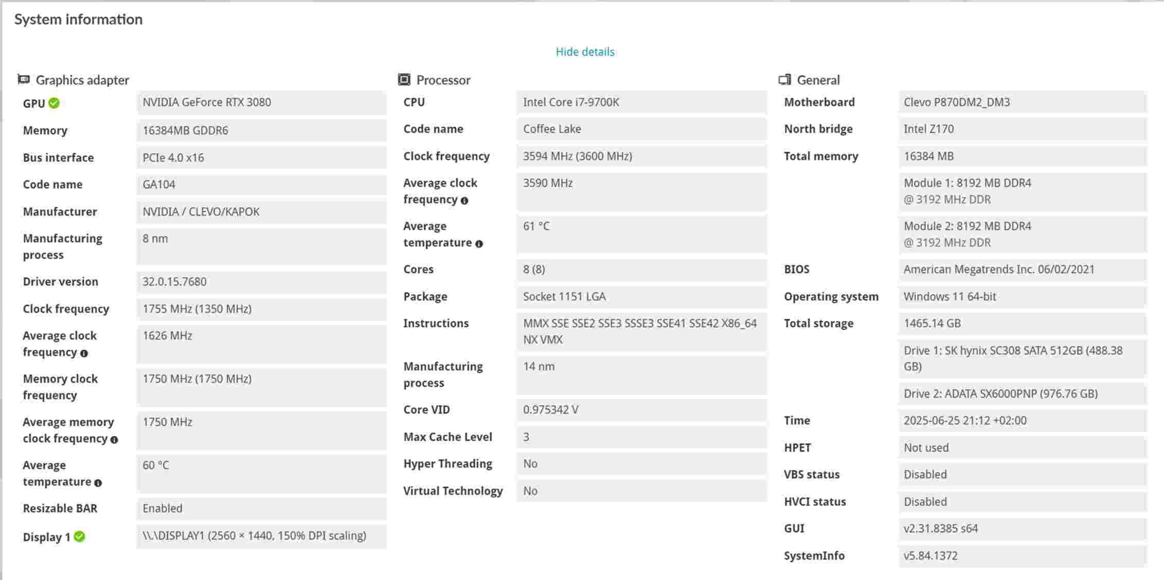
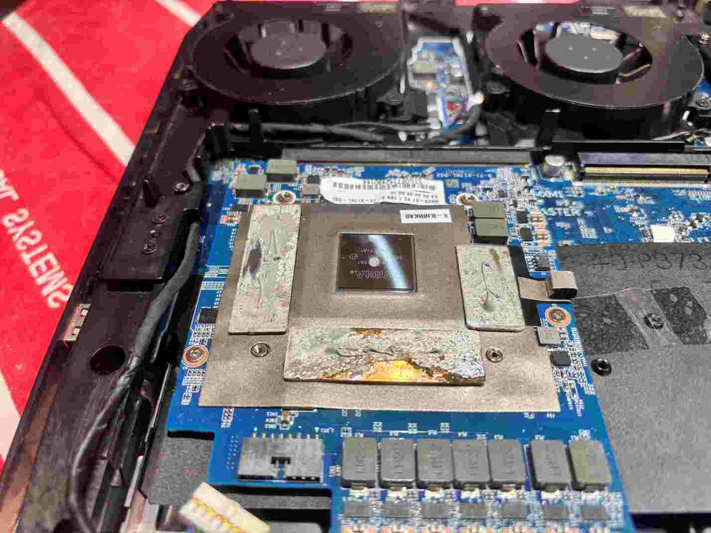
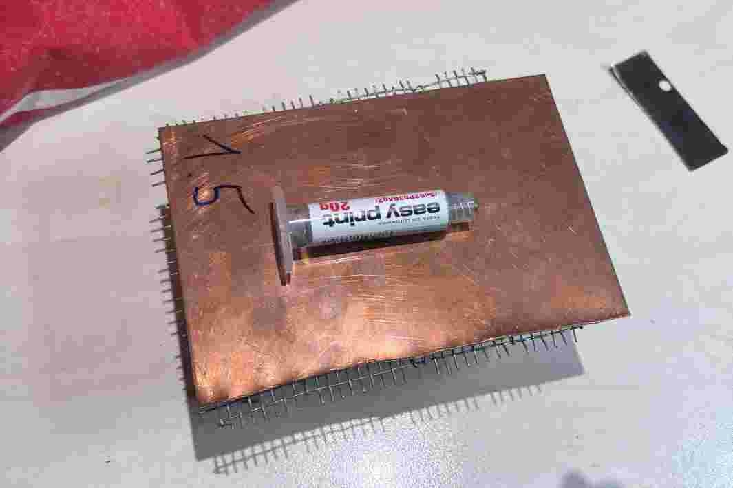
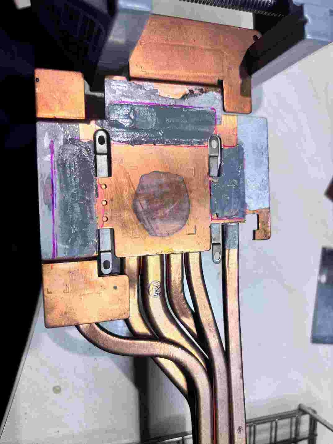
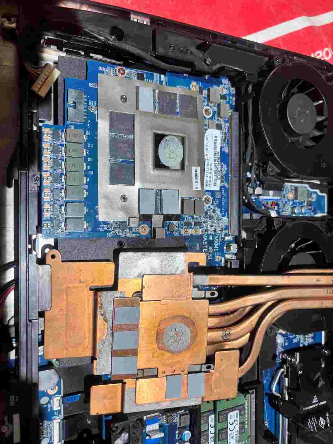
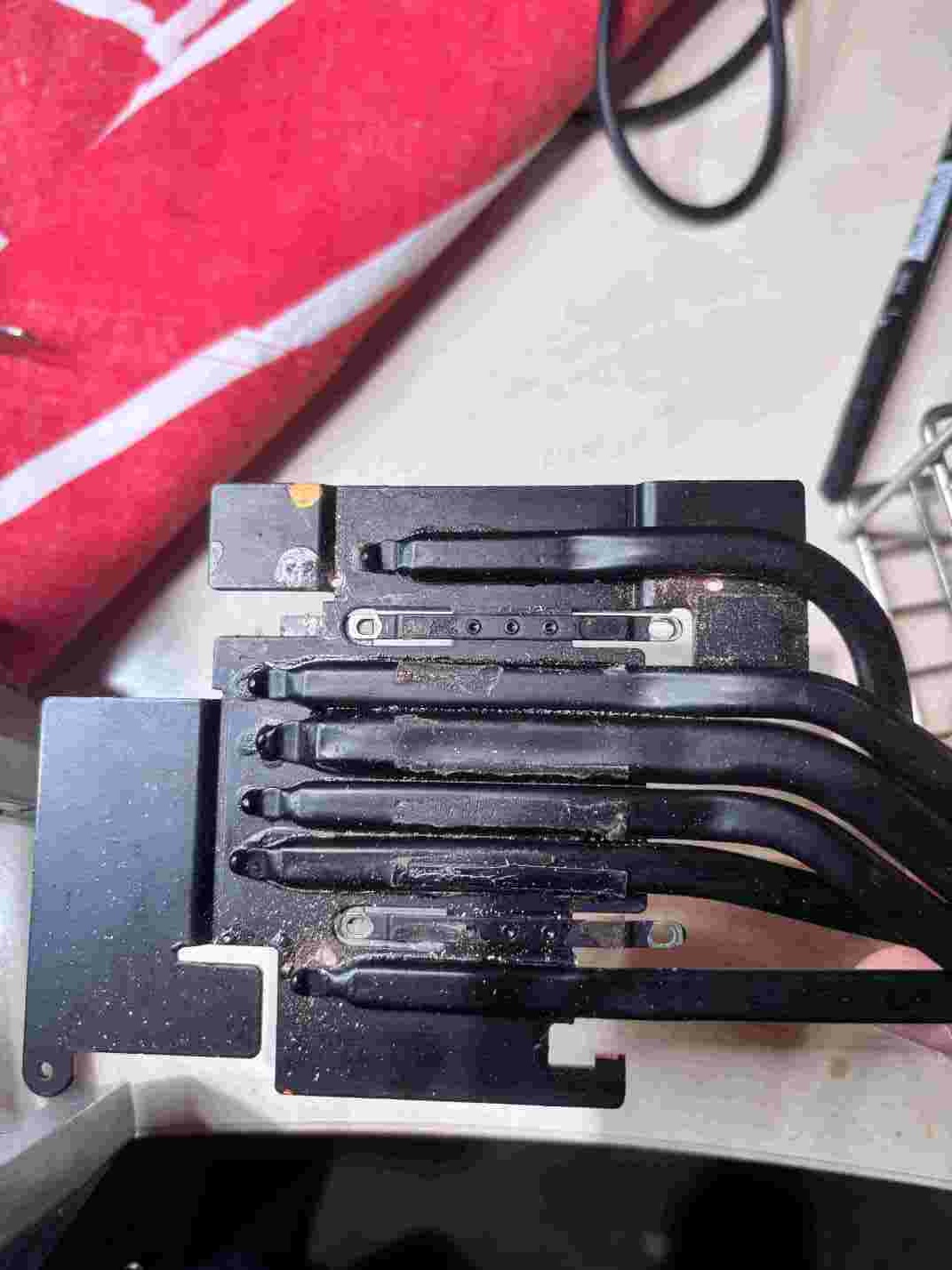
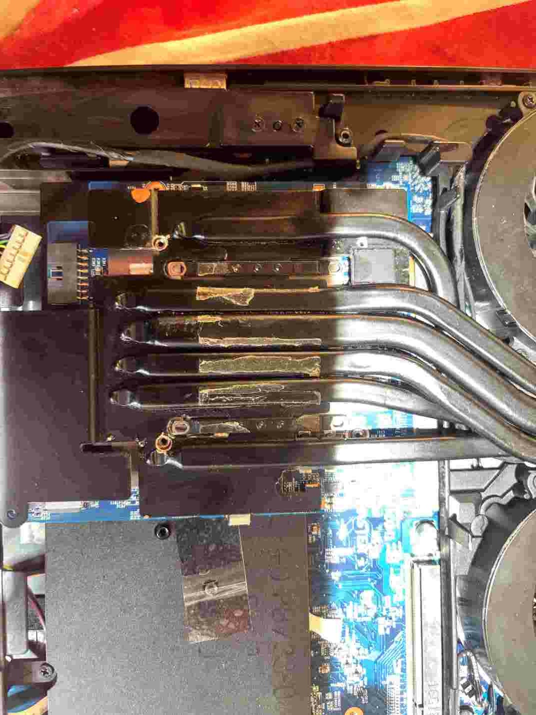
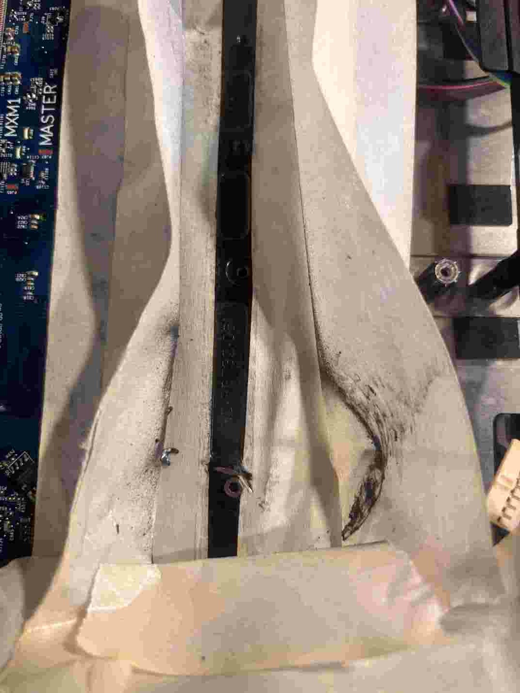
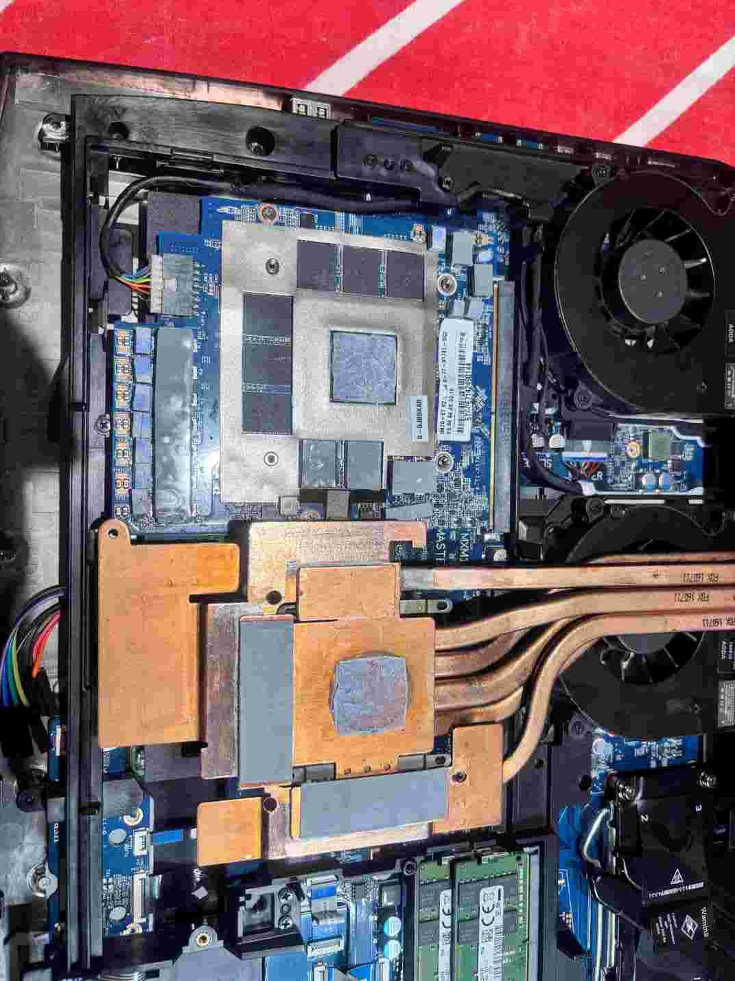
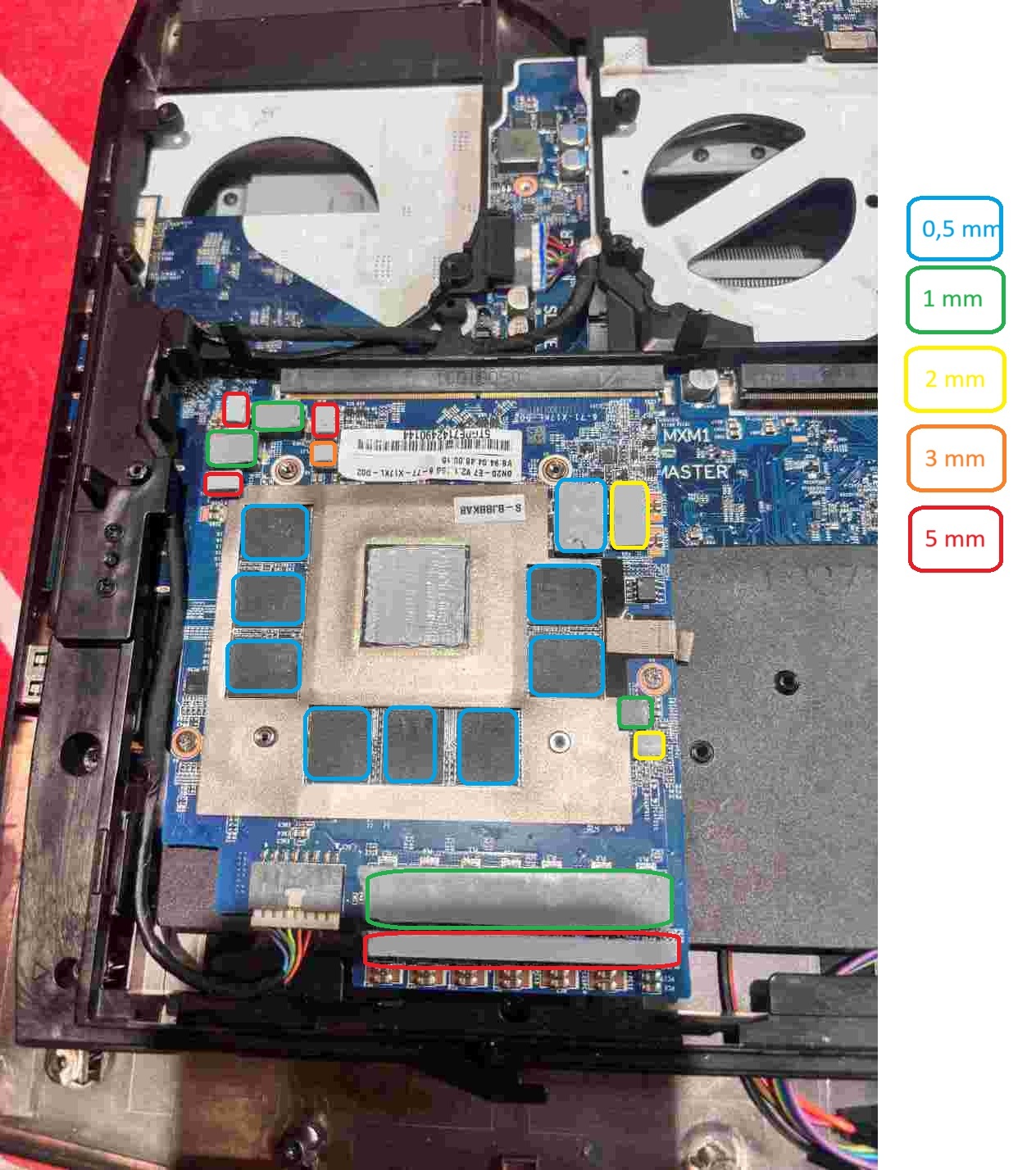
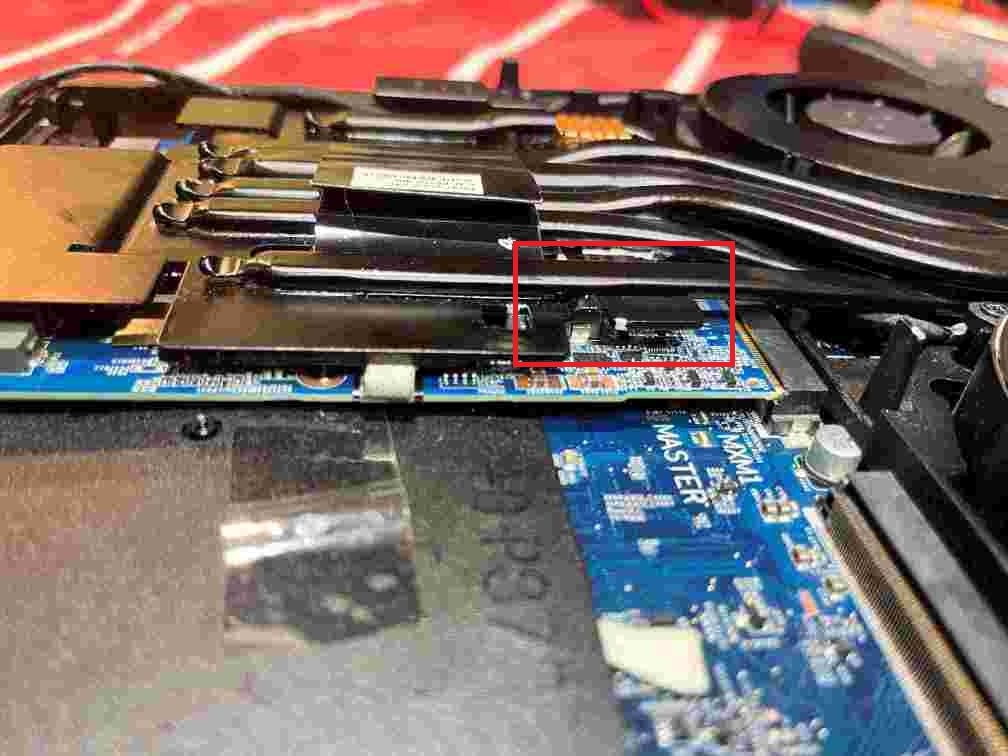
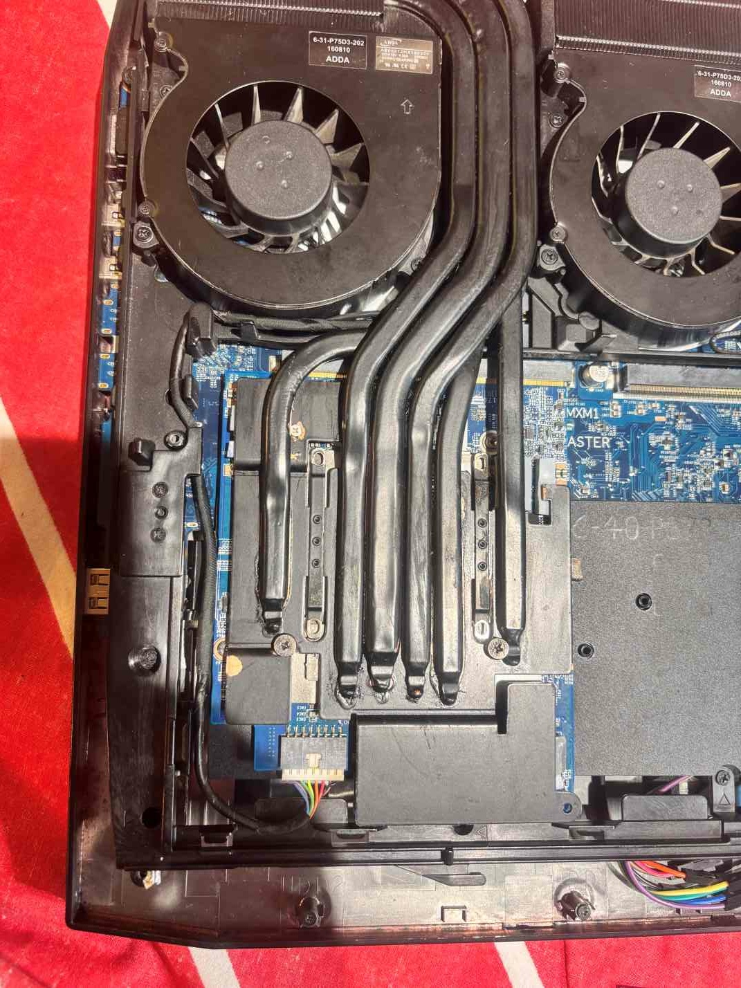
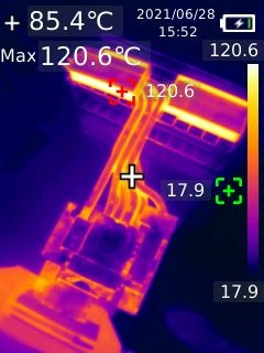
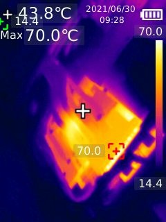
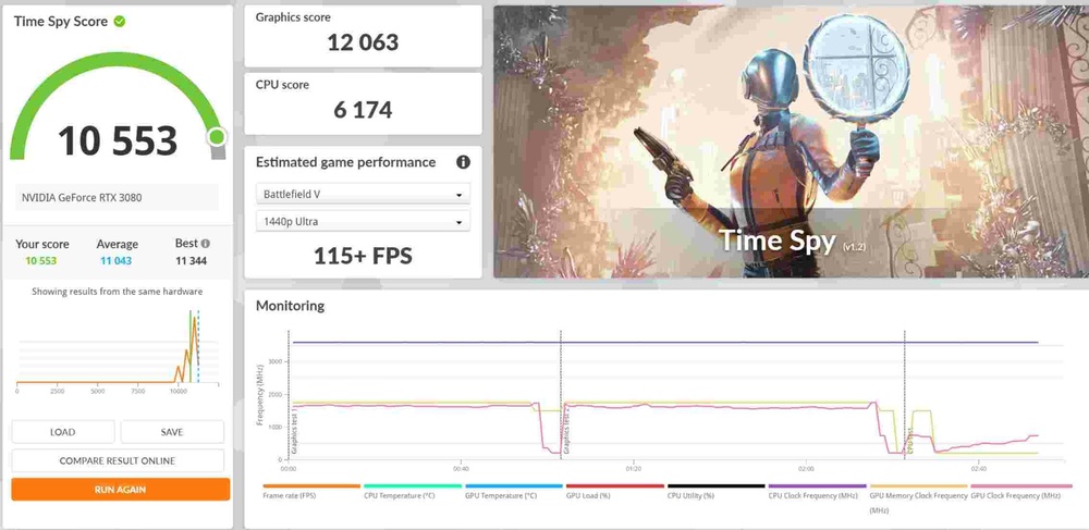
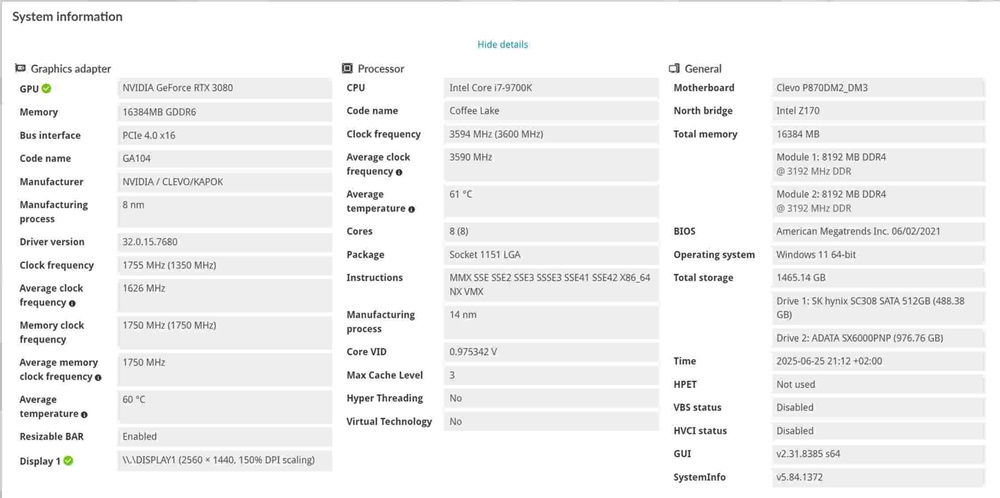
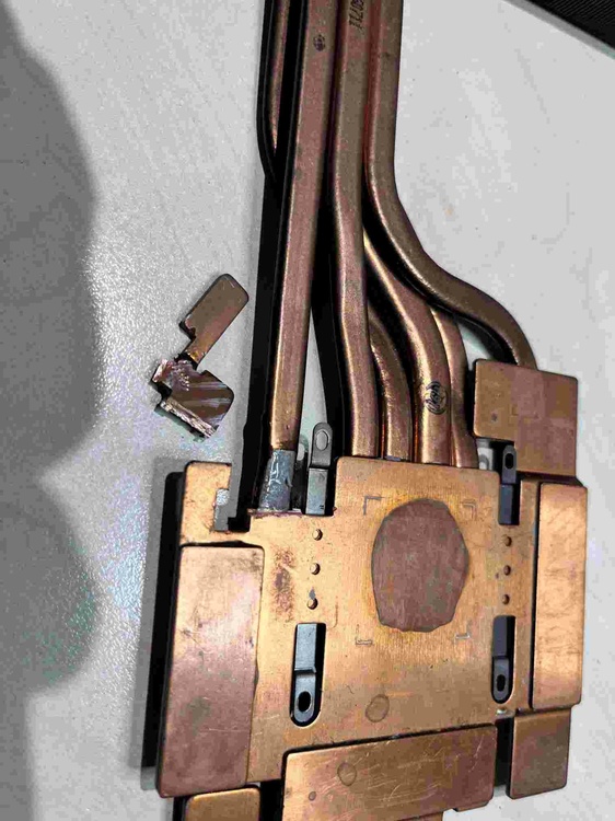
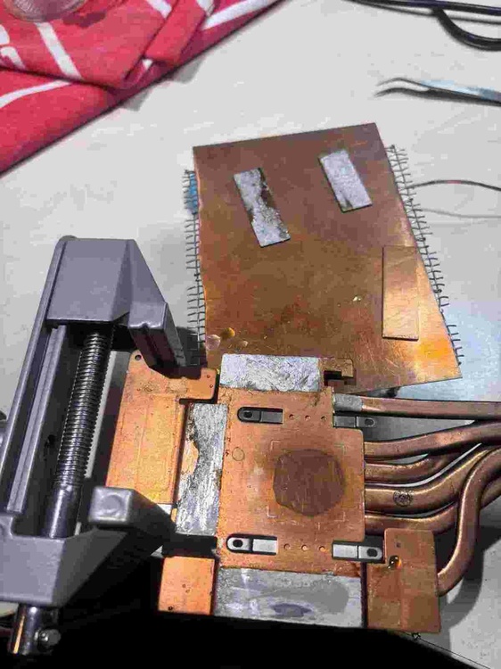
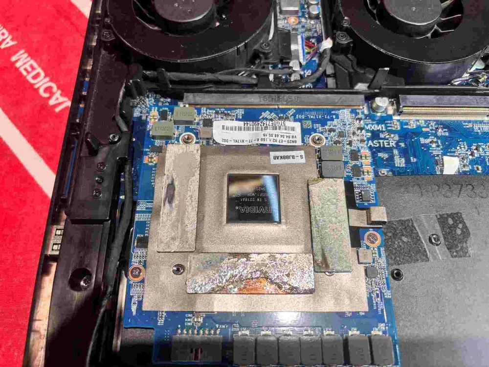
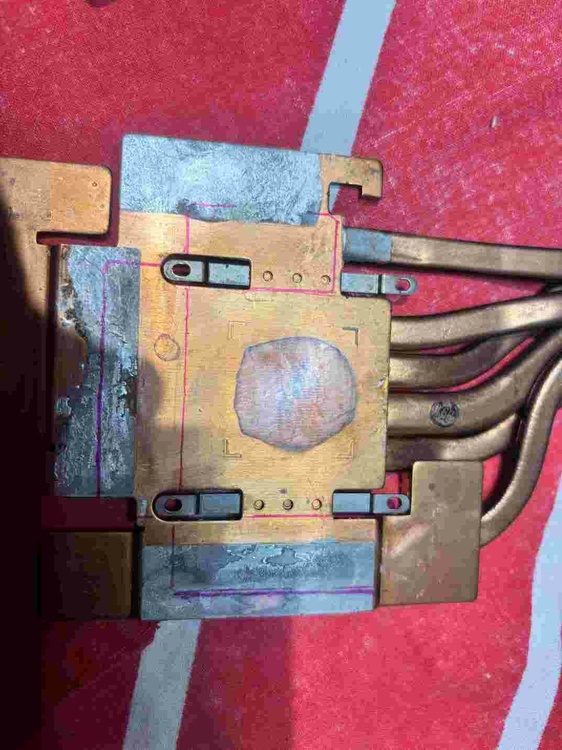
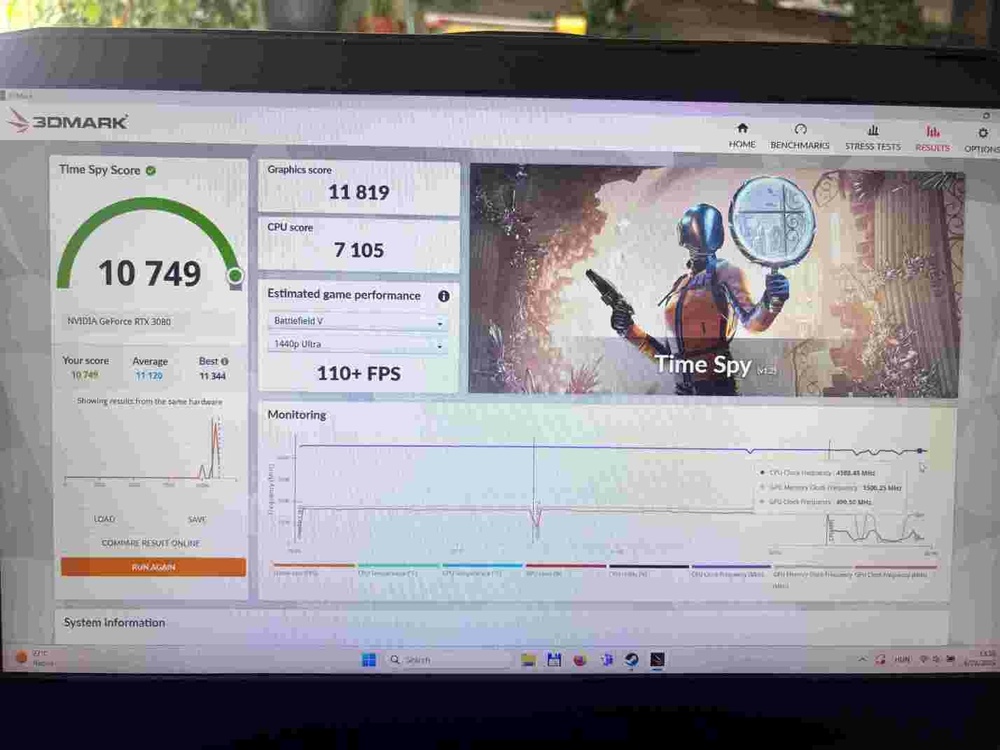
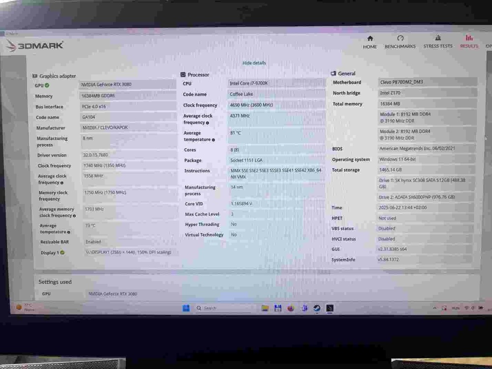
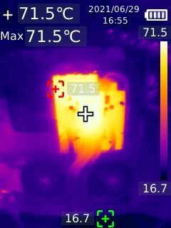
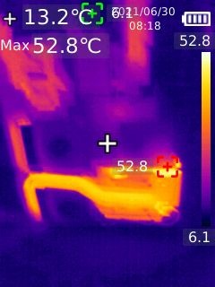
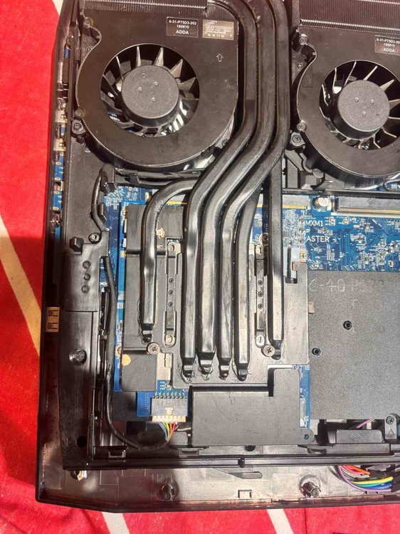
Hi All, First off all thank you all in the forum to share with us your knowledge and experience! I would like to share with you how I tried to mod my T-shape heatsink to install RTX 3080 to P870DM2. I have a this P870 since 2021 before that I had an P751DM2, then I replaced 6700k to 9700k. I also did the easy BIOS chip access mod. For this work I used: Hot air blower (industrial) Solder paste Dremmel. Screws Isopropyl alcohol, compressed air 0,5 mm, 1 mm, 2 mm, 3 mm Gelid extreme pads Before soldering all parts was cleaned with alcohol. Hot air setup: 500 C, mid flow It took about 8 hours. I have a hot air for soldering but it was useless, had to use 2000W for the work. First I hed to cut down old MXM card holder, because it was touching the new card. I was lazy not to remove the motherboard but I used adhesive tape to hold as many metal dust as I can. After I used compressed air to remove what left of them. There is 2 place where the inductors are too high, for one of them I needed to cut. I just cut with the dremmel to see the solder and try to not cut the heatpipe. I heated up with hot air, then broke it down. I wanted to use the orginal copper(1 mm) for VRAM so I removed them. It took about 20 min to heat up the whole heatsink. I placed the heatsinks on the VRAMS then I saw I had to cut one of them to be shorter. Used and old thermal paste which I am no longer using and "glued" back to the heatsink. I marked the heatsinks places and used solder paste because it is easier to apply on the surface. Then I soldered them to place. It took me about 30 min. For VRAMs I planned to use 0,5mm pads, for test I used the old ones from the GTX 1080. I applied some thermal paste on the GPU to check the distance. I drilled the holes (3 mm) for the new screws, I did not do a good job. It was not well aligned since I not measured just drilled on sight. I planned to solder back one piece of copper on the heat pipe for the 4th screw but I could not do it. So I continued with 3 holes after all. I measured the components height that I think it should be cooled. VRAM Inductor 4mm Vram IC 1mm VRAM 1mm 5V rail inductor 2mm 5V rail IC 1mm GPU Inductor 4mm GPU Rail IC 1mm Basically all IC 1mm, big inductor 4mm, small inductor 2mm. Here is the pads thickness I used. I noticed the whole heatsink was bent, because the work, I bent it back. It can be seen the paste is not evenly distributed. I used some old screws with spring on 2 place and one without it. Here is the final work. After all the work I tested the system and I was really not happy with the results. It seemed all the heat up with the blower vaporized the gas from the heat pipes. The heat distribution just not worked well. There were a lot of thermal throttling at the test. On the thermal camera it can be seen the heat pipes are not working. I was really sad that I had work for nothing and wrecked the heatsink. However after a day and after a few days it seemed the heatsink started to work. I have no idea how does it possible.. If someone could explain me a the physics of this it would be great. The result are here it seems to be a bit low score. With automatic fan control the average 73 C. With full fan the avarage 60 C. During whole test the power limit is on.


-
On second thought AUTO setting does not matter it just adjust which one test first.
-
If you sure that you have the latest BIOS for the iGPU even that I think rewriting the latest BIOS with the programmer is a good step. If you have an older BIOS then I assume the iGPU will not work. The programmer itself cheap comparing to any hardware and it is pretty easy to use. You already suspecting the motherboard faulty there is nothing to lose to try. If the default setting for iGPU is auto and you remove the GPU then the system should post with iGPU. ( I think) Need someone to confirm the teory since I do not have x170. What is the latest BIOS? Is iGPU setting is AUTO on default?
-
This is what I found, If you have the latest BIOS you have iGPU setting. I have P870 it does not have iGPU. Also you could try flashing a BIOS If you have CH341A programmer.
-
Hi, I think x170 does not have iGPU just like P870. It is more likely based on the sympthons that the GPU is faulty. Because the fan speed change and keyboard lit, it seems the EC should work. For the BIOS/EC work the CPU should be working. I am no expert either but I would test the GPU first.