
janepa
-
Posts
76 -
Joined
-
Last visited
4 Followers



janepa's Achievements






-
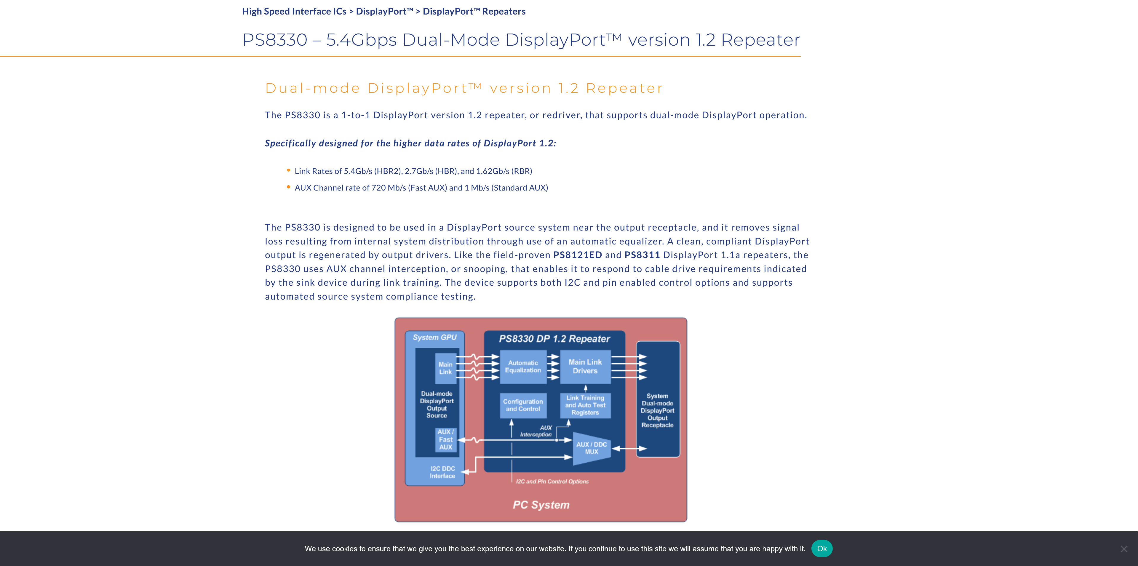
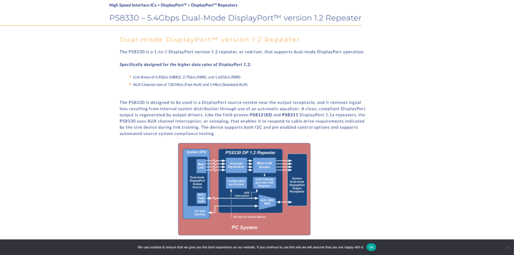
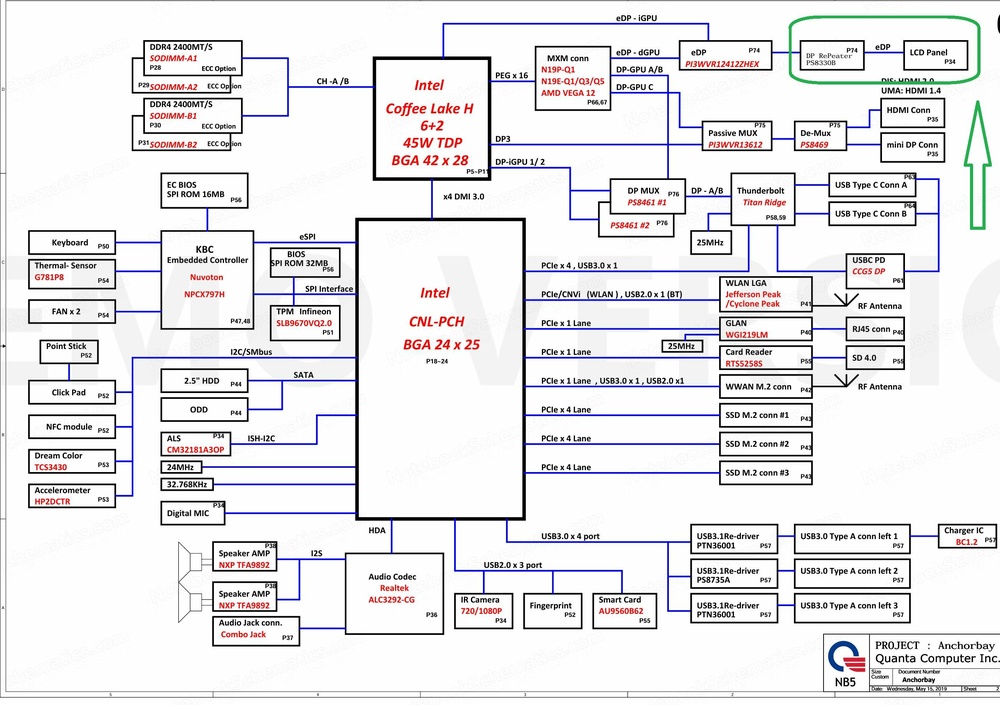
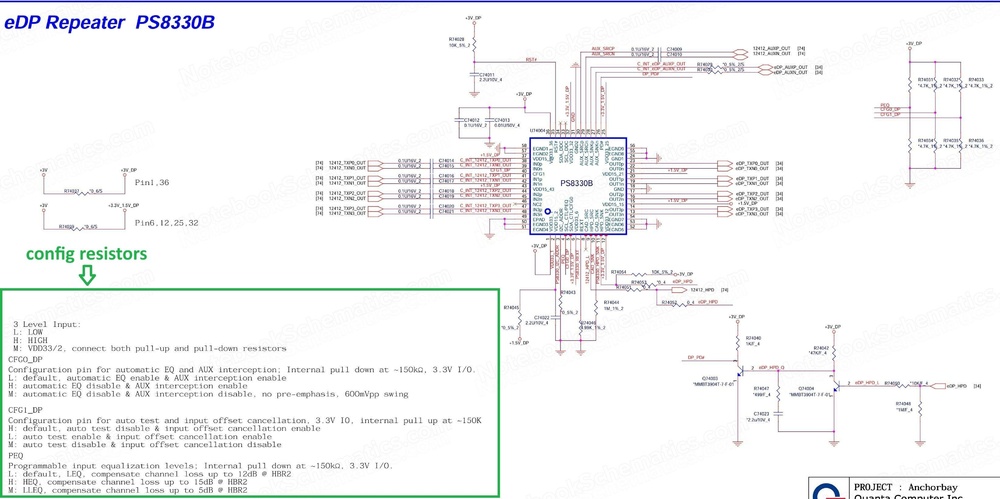
Good point. Yes, that’s correct, but there are many different types of redrivers on the market including versions without the MUX function. Perhaps to simplify the explanation, it’s more practical to use a MUX switch and redriver in a single IC for several reasons, such as cost, simpler design, etc... For example:
-
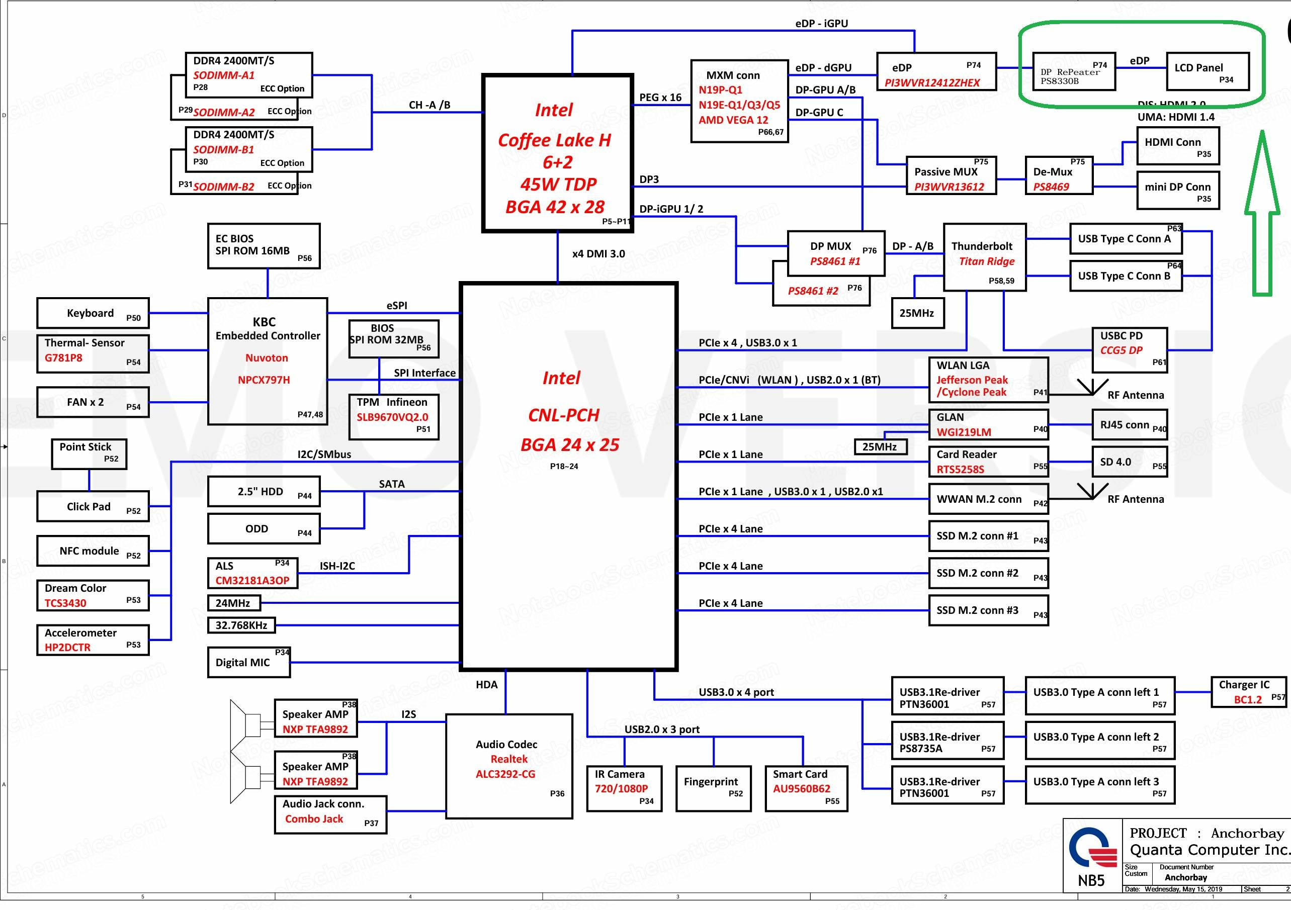
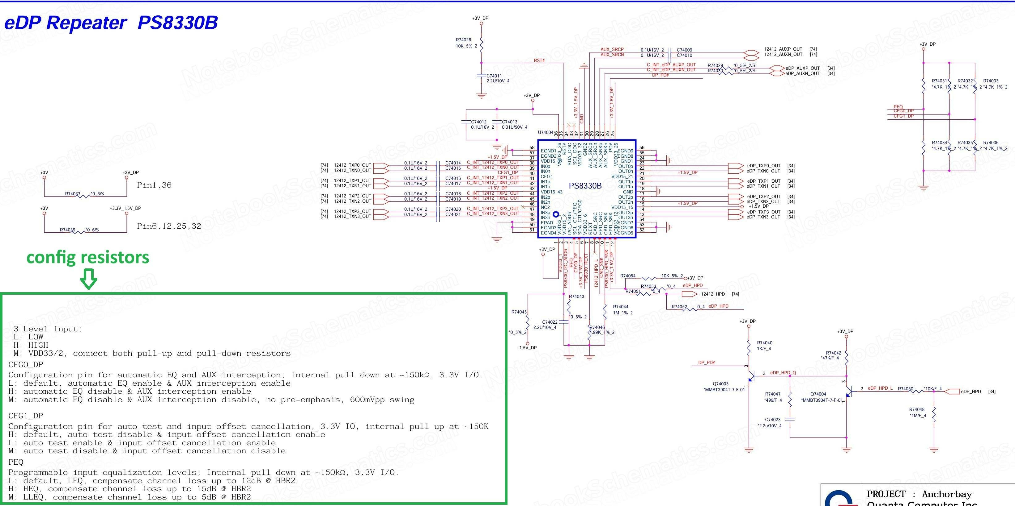
Yes, that's right. DisplayPort + pins for controlling the LCD display = eDP (Embedded DisplayPort) The problem is that most older eDP LCD displays (with internal EDID EEPROM memory inside the LCD) only work with (standard or normal) DP. But newer GPU cards, which of course no longer have the settings for connecting to the primary internal display LCD (eDP settings) configured in the VBIOS automatically support newer generations of DP (usually DP++). So due to communication via AUX lines (similar to I2C serial communication) between the LCD and the graphics card, which is part of every DP connection a “black screen” issue occurs after installing the drivers. Newer-generation LCDs (with internal EDID EEPROM memory) (VESA v1.4a) should support DP++, however the laptop manufacturers usually prefer to play it safe and insert a so-called: DP-redriver between the LCD and eDP lines, which can usually be configured using resistors to ensure a wide range of compatibility. However, there is another option. Since LCD displays typically use standard i2c eeprom memory to store EDID data, which as I mentioned communicates via AUX (I²C) bus with the GPU this offers the possibility to experiment directly with the EDID itself (for example by changing its parameters). Various versions of EDID editors are available online some even include a function to generate a new EDID data (which generates new EEPROM content after entering the input parameters). For the purpose of determining these input parameters tools such as the DTD Calculator are useful it is also often included in some of the more sophisticated editors. or There is also the option to experiment using so-called “DisplayPort dongle emulators,” which contain nothing more than the previously mentioned standard 24CXX-type serial EEPROM with modified contents. I’m just trying to point out a possible way to try to rescue one of the disabled (unusable) DP_x GPU outputs. Yes, a long time ago I worked with electronics in cars for example: EDC and Me engine control units including even the very old (non-flashable) ones and many other components used in cars, so I have experience with SMD and even hybrid components sealed in gel that were used in VP fuel injection pumps. But that was really a long time ago. I gained a bit more experience with motherboards during the project to convert my AW M18x R2 from an LVDS to an eDP system. I’ve made a lot of mistakes during my experiments and damaged the motherboard many times and I’ve had to replace a lot of components. But every time I managed to bring it back to life even though it sometimes took a really long time. I agree, resistors, ceramic capacitors, CMOS logic, that’s true I know. Thank you for your support. Any advice is helpful.
-
No, DP is the same on both platforms. The only difference is in the DP generation: DP, DP+ and DP++.
-
Great, thanks for the support.
-
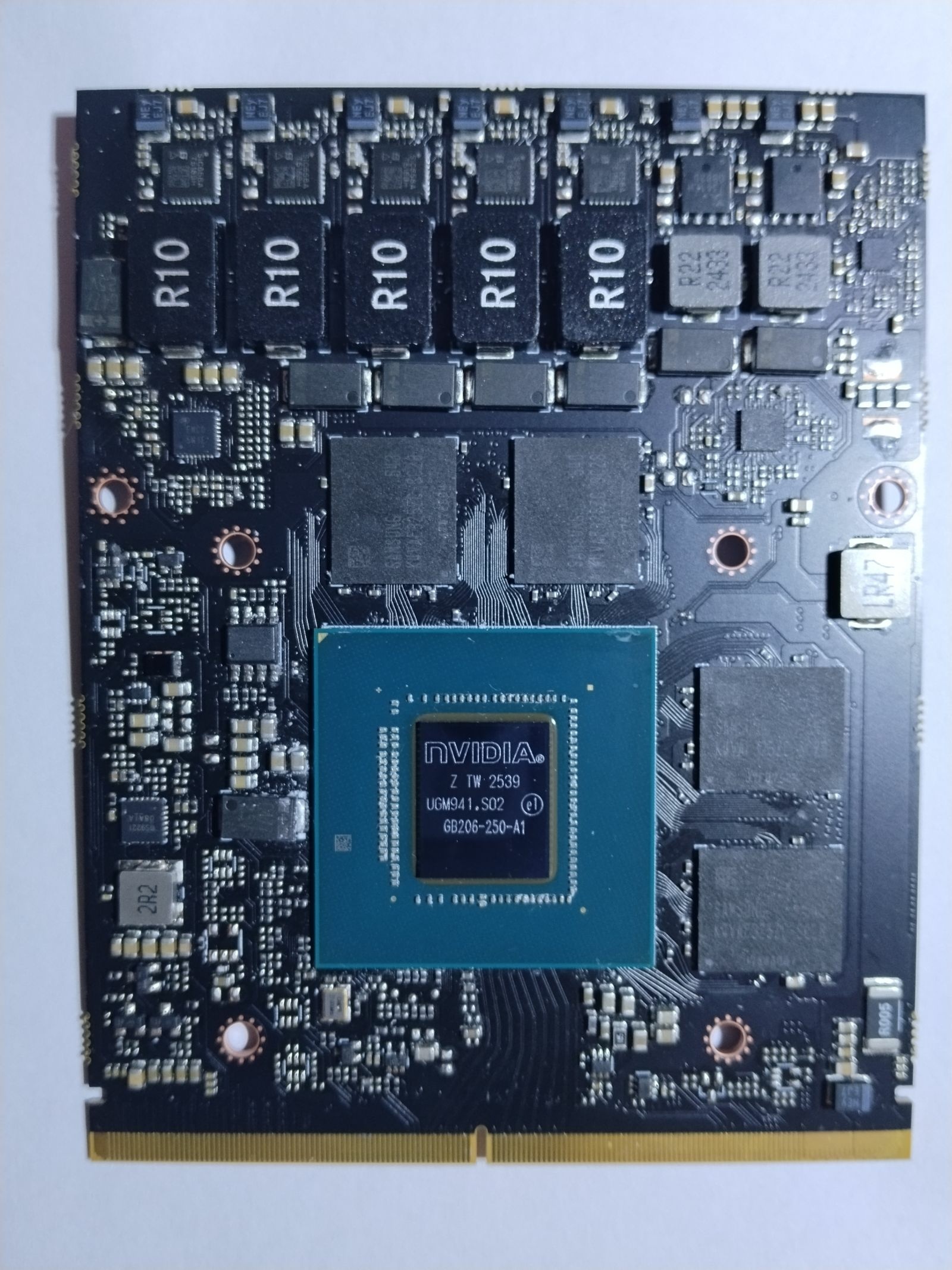
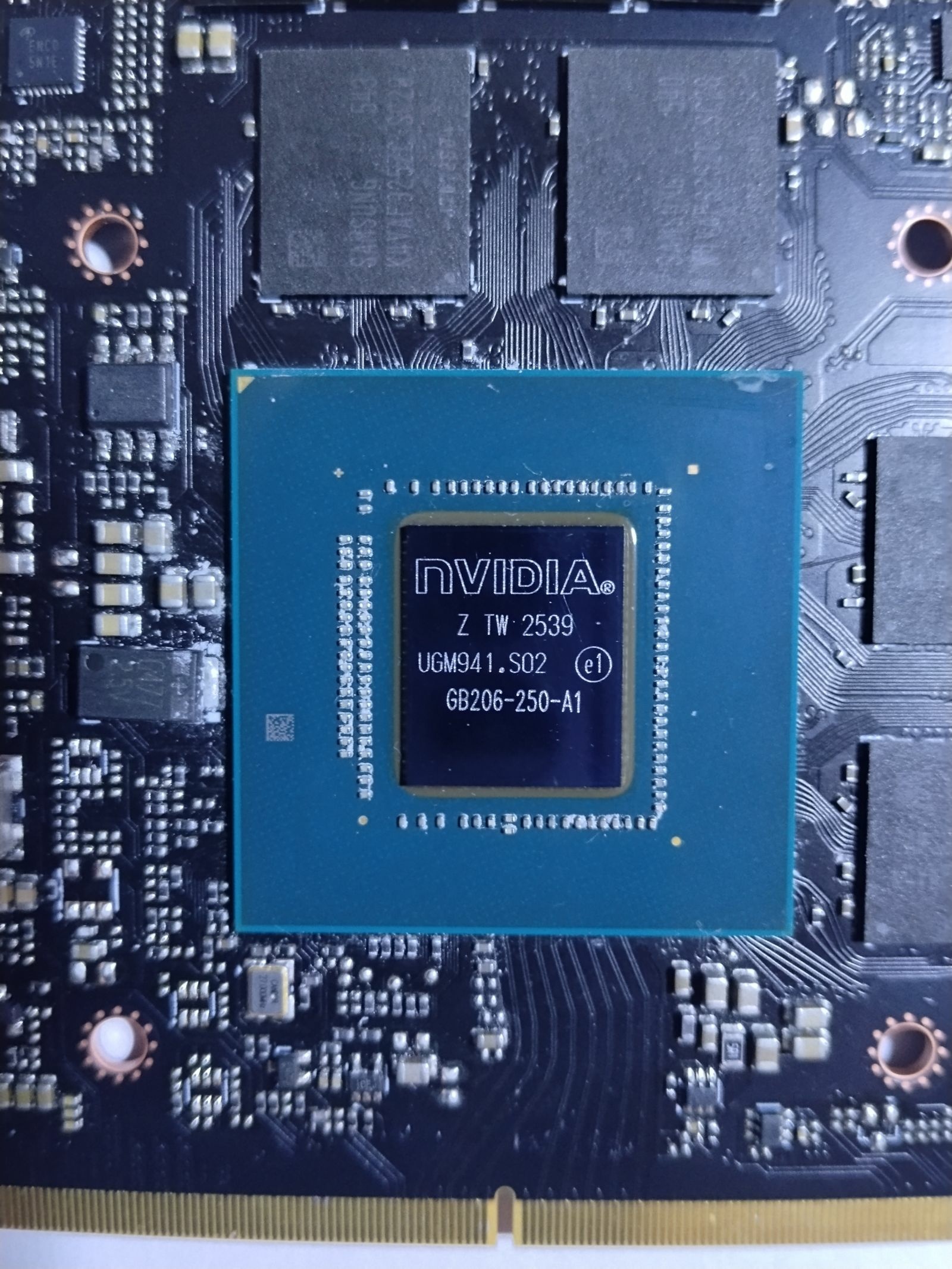
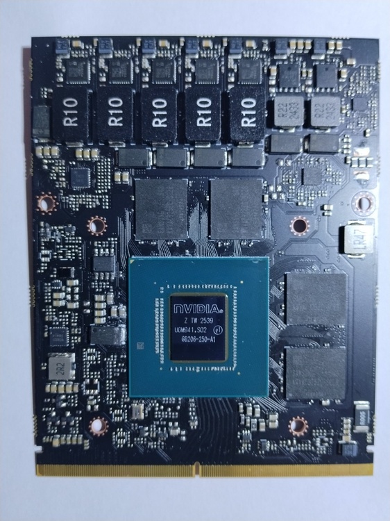
Hello. This card looks like an early sample or ES of the 5060 by looking at the VRMs. They took the B design rather than the A design. Well, anyway I’m pretty surprised that they used a desktop core here. I’ve never seen anything like this not even in a photo. Did you check the VBIOS? To find out the TDP and display settings? It looks like it has a 145+5W TDP, 3xDP, and 1xHDMI. The TDP power slider and fan RPM slider are available here too. Since this is an integrated graphics card, you need to enable the backlight pins and, if possible, add PWM brightness control. That's no problem for me. Is the 5060 model on par with the 4070? Hard to say. I think sliderfra has an eDP R3/R4 cable. Thanks, I already have it. My R4 has an RTX 3080 16 GB card in the PEG slot; there’s no need to upgrade it because of the processor and its lack of support for the latest instructions. So what would you recommend? Is this a waste of time? I’m just pointing out that if the modification is successful, it could then be implemented on other platforms with newer CPUs of course.Maybe this could be useful for the people here looking to the future.
-
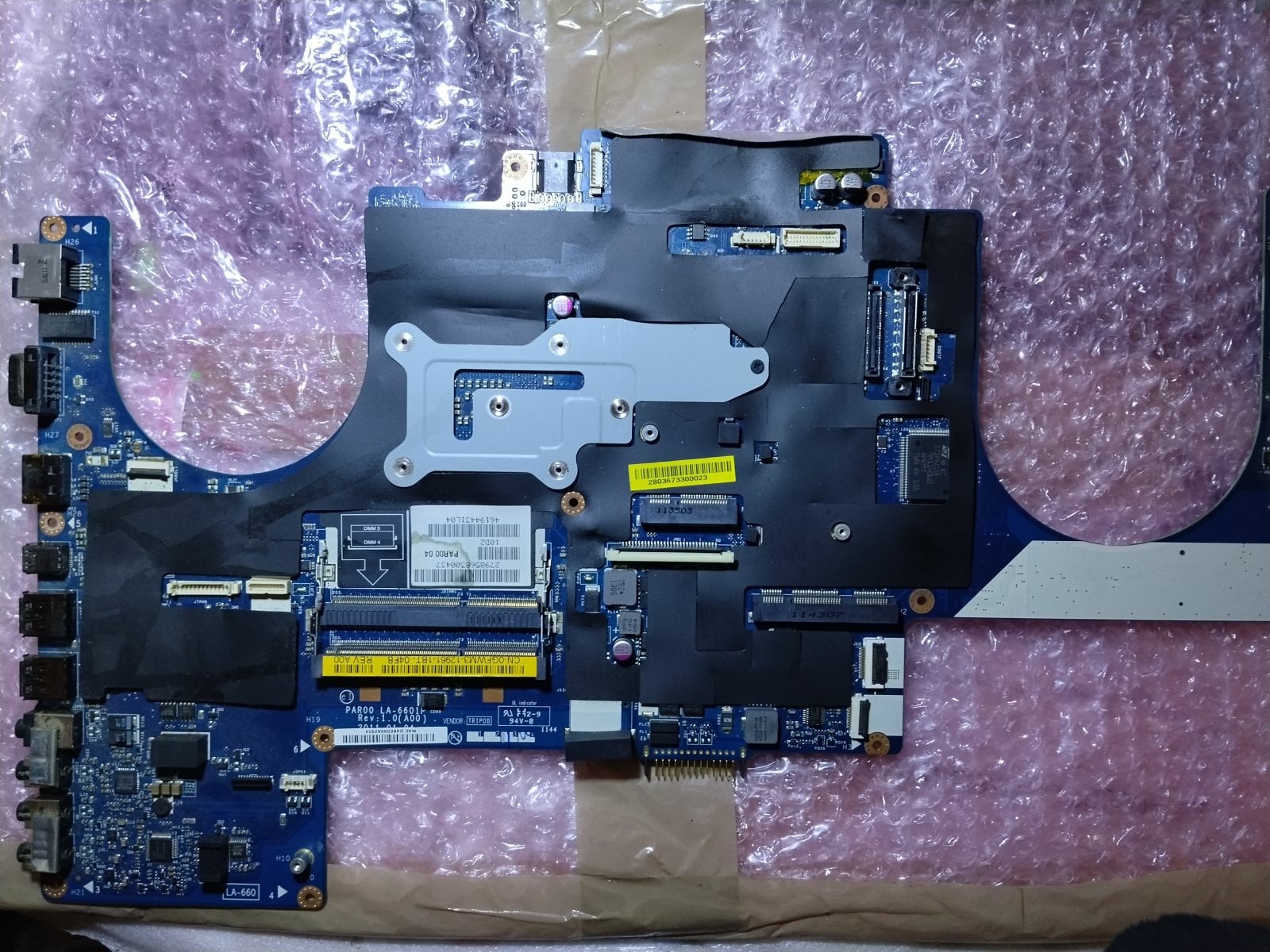
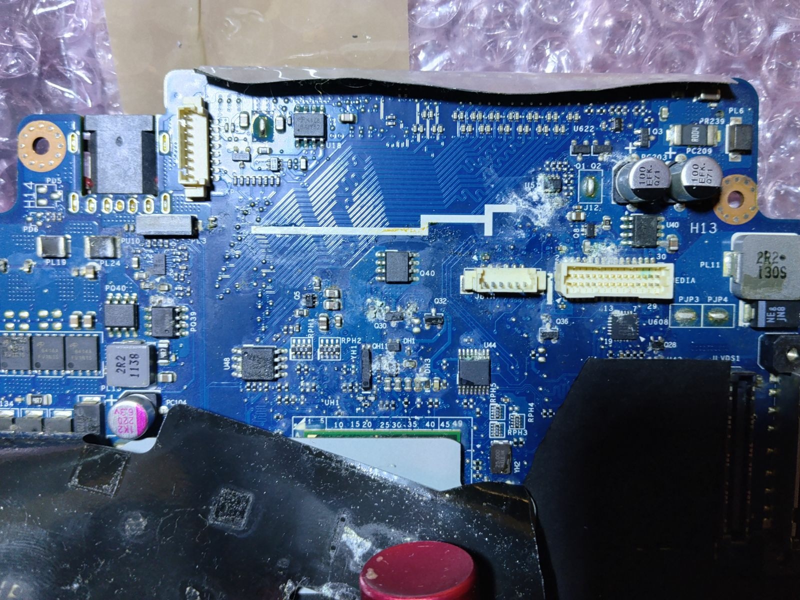
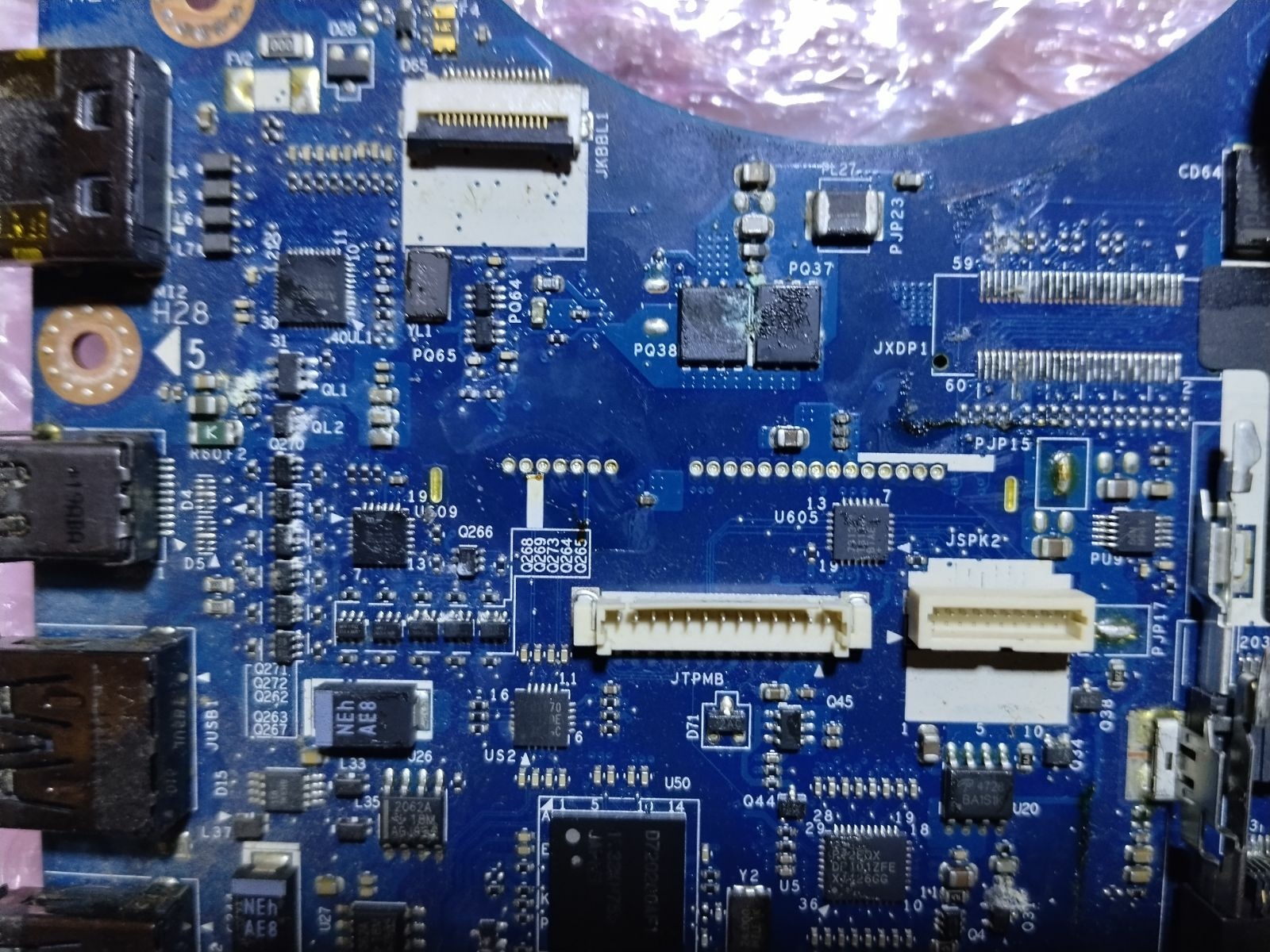
Luckily I managed to get this GPU card through a barter trade at the local market. I'm not sure if I'm seeing correctly or if I'm going to mad, but take a look at the NVIDIA GBxxx chip number. I also bought a damaged M17x R3 motherboard very cheaply, so I will repair it and try to get running that card on this platform by modifying the BIOS. I will use a 14" 2K 165Hz eDP LCD display since that's the only one I have. That's the little idea. Does anyone know where I can get a cheap 40-pin eDP cable for the R3 or R4? I'm assuming it's the same for the R4 model.
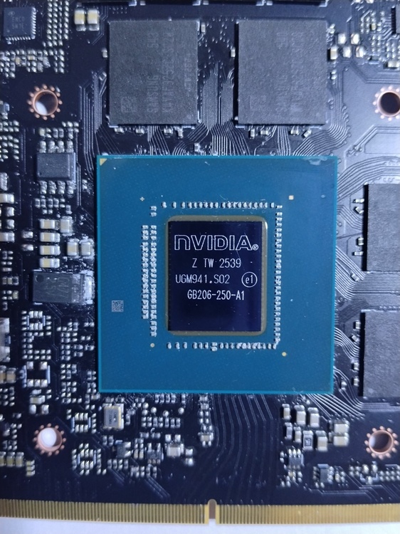
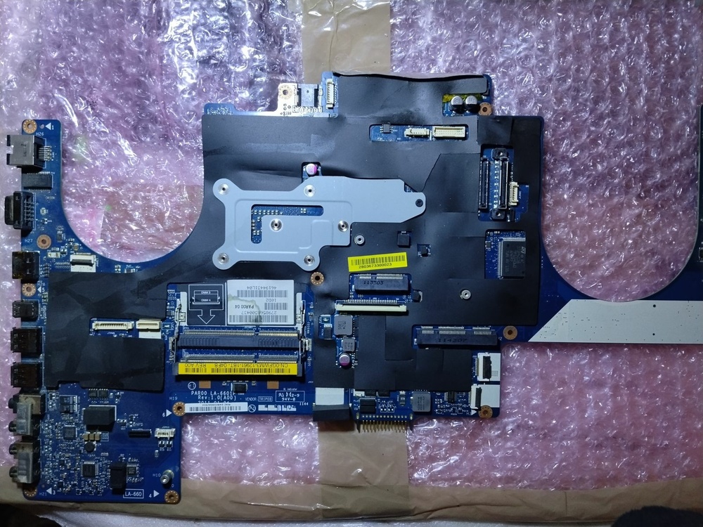
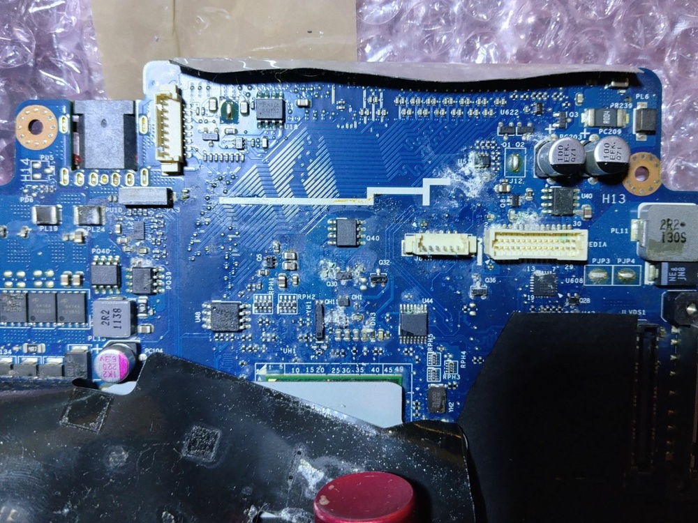
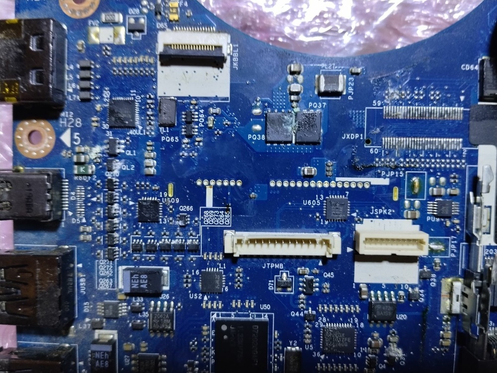
-
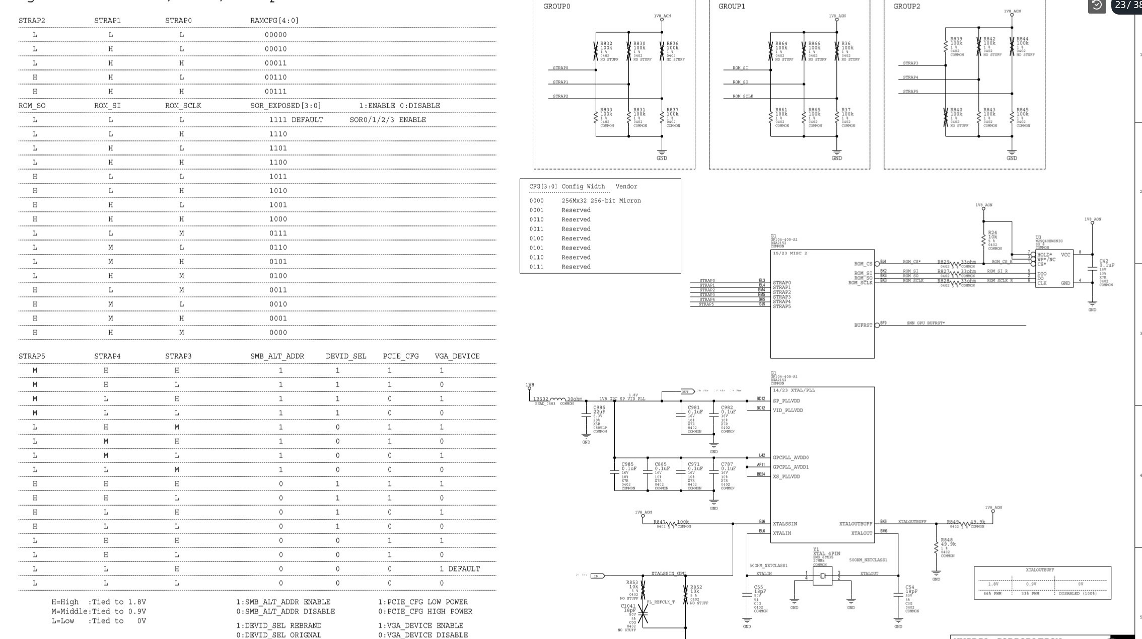
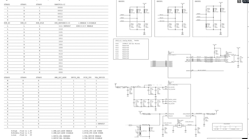
No, there's no need to modify the VBIOS. There are resistor straps on the PCB that are used to set the VRAM size after replacing them with higher capacity memory. There are multiple resistor straps on the PCB, and they are used to modify various parameters on some models, such as TDP, graphics output settings, etc. https://www.google.com/search?q=gpu+resistor+strap&sca_esv=0adcf06bd624d4eb&hl=cs&udm=2&biw=1984&bih=988&sxsrf=APpeQntxCWskxgYSVTVhZkl-licBbMTxXA%3A1791440046190&ei=rjTHasikC5Hj7_UPj72GWA&ved=2ahUKEwjIs9uc4qmXAxWR8bsIHY-eAQsQ4dUDegQIBhAN&uact=5&oq=gpu+resistor+strap&gs_lp=Egtnd3Mtd2l6LWltZyISZ3B1IHJlc2lzdG9yIHN0cmFwSOwwUPkcWMEscAN4AJABAJgBxAGgAbIEqgEDMS4zuAEDyAEA-AEBmAIEoAKvAcICBBAAGB7CAgYQABgIGB7CAggQABgIGB4YCsICChAAGAgYBxgeGAqYAwCIBgGSBwMzLjGgB6QBsgcDMC4xuAejAcIHBTAuMy4xyAcIgAgB&sclient=gws-wiz-img
-
ADLINK RTX 3000 MXM suddenly died?
janepa replied to Hussain Alhadher's topic in Alienware 17 and M17x
I understand, they’re right. Sometimes it’s really difficult and takes a very, very long time to find the fault. Sometimes the quickest fix is to replace the motherboard, but it depends on the situation of course. The only thing that comes to my mind that you can do yourself at home in this case what I remember a similar situation where (I’m not sure if it was an R3 or R4) the system started running unstable after an emergency shutdown, what helped was flashing the EC controller’s flash memory for example using a CH341A programmer. But that’s about as far as you can go at home and it costs almost nothing, just a little time. -
ADLINK RTX 3000 MXM suddenly died?
janepa replied to Hussain Alhadher's topic in Alienware 17 and M17x
Hi, yes of course there’s nothing special about it. However this only applies if your card shows the exact same symptoms mentioned here. Before you begin I recommend practicing the procedure a bit first, because you’ll need to work very quickly when searching for the defective component. So first using the IPA spray mentioned earlier create a thin layer of frost on the card (simply spray until it becomes visible). Second very quickly connect two half-discharged batteries in series (these will replace the lab. power supply and since the internal resistance of a half-discharged battery is high the voltage will immediately drop to a few tenths of a volt under load, but the current will be sufficient) using pieces of wire to the card’s power contacts (be careful to observe the correct polarity, otherwise the Zener diode will trigger and the test will be ineffective). Very quickly after connecting the batteries the fine frost on the defective (short-circuited) component will immediately melt due to the heating and that’s all. Dry it by blowing on it or using a paper tissue for example and repeat the process from the other side. If the test result is unclear add another cell a half-discharged battery and repeat the entire process again. If it’s just a small ceramic capacitor, you can remove it mechanically. For other components unfortunately, you’ll need a hot air gun and a soldering iron. (Instead of IPA spray, I prefer to use a vaporizer with soldering rosin and it’s worked perfectly for many years. A thermal camera does a good work too. I use a Diametral lab. power supply and a METEX multimeter both of which have been running without a single issue for 25 years just for the curious. ) -
Hi, this might sound a little weird, but I’ve already encountered something similar a few times and when I wasn’t completely sure if reballing would help, I put the card in an electric oven for 10 minutes at 180 °C. Maybe the artifacts will disappear then. But it’s also possible that one of the memory chips is defective. The GPU core temperature might be very low, but that doesn’t mean the VRAM temperature is the same.
-
ADLINK RTX 3000 MXM suddenly died?
janepa replied to Hussain Alhadher's topic in Alienware 17 and M17x
Okay, first we need any ordinary contact cleaner spray based on isopropyl alcohol. There are tons of options on the market, but it has to be a pressurized can not a manual sprayer. Second you’ll need two or better three nearly dead AA or AAA 1.5V battery cells like from a TV remote control plus two pieces of any kind of wire or even a paper clip will do. If it's (in the best case) just a shorted ceramic capacitor it can be removed mechanically for example with a small screwsdriver and no soldering is needed. There are lots of them and the card can operate without one as well. No worries. Any ordinary inexpensive basic multimeter is obviously a big advantage, as other forum users have mentioned here. -
ADLINK RTX 3000 MXM suddenly died?
janepa replied to Hussain Alhadher's topic in Alienware 17 and M17x
Hi It could be any of those of course. I can try to help you in the simplest way I know. If this is still relevant. -
HP Elitebook 8570W - is it still good ? Hardware modifications
janepa replied to GuitarG's topic in Custom Builds
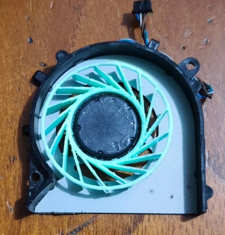
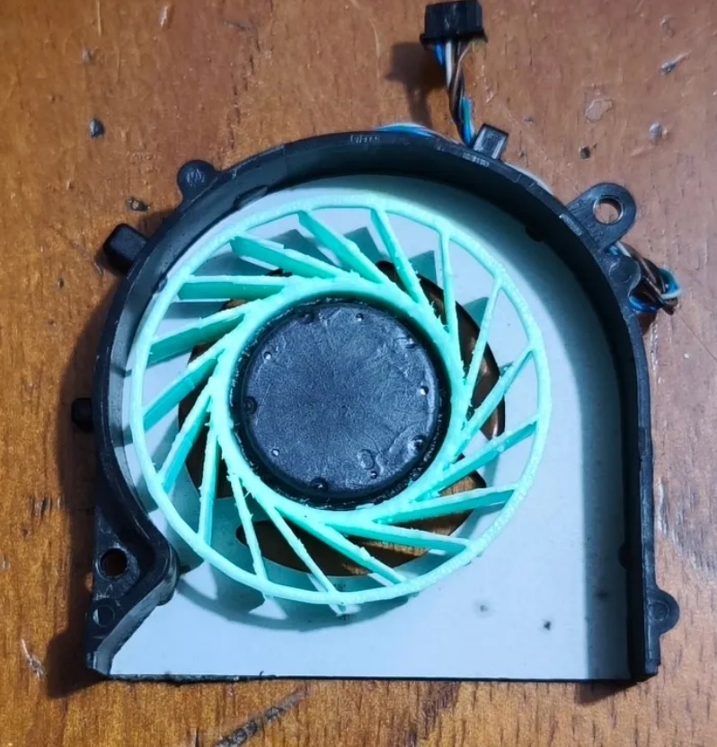
Yes, years ago I built a similar model with a loop and it worked well, but in the end I decided to go a different way because of easier installation and removal needed. Your idea is also possible of course. There are several options available. No, this is the original fan that was damaged it was missing a few blades it was basically a scrap. Here you have the option to remove the all original blades keep the fan core and attach a newly designed ring with blades shaped as needed. I also had a problem controlling the fans, but I eventually solved it by using my own small control electronics. -
HP Elitebook 8570W - is it still good ? Hardware modifications
janepa replied to GuitarG's topic in Custom Builds
Hotspot temp. sensors on a GPU chip.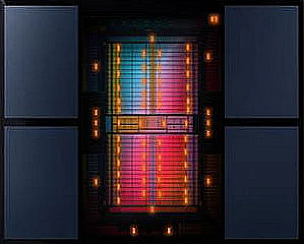
-
HP Elitebook 8570W - is it still good ? Hardware modifications
janepa replied to GuitarG's topic in Custom Builds
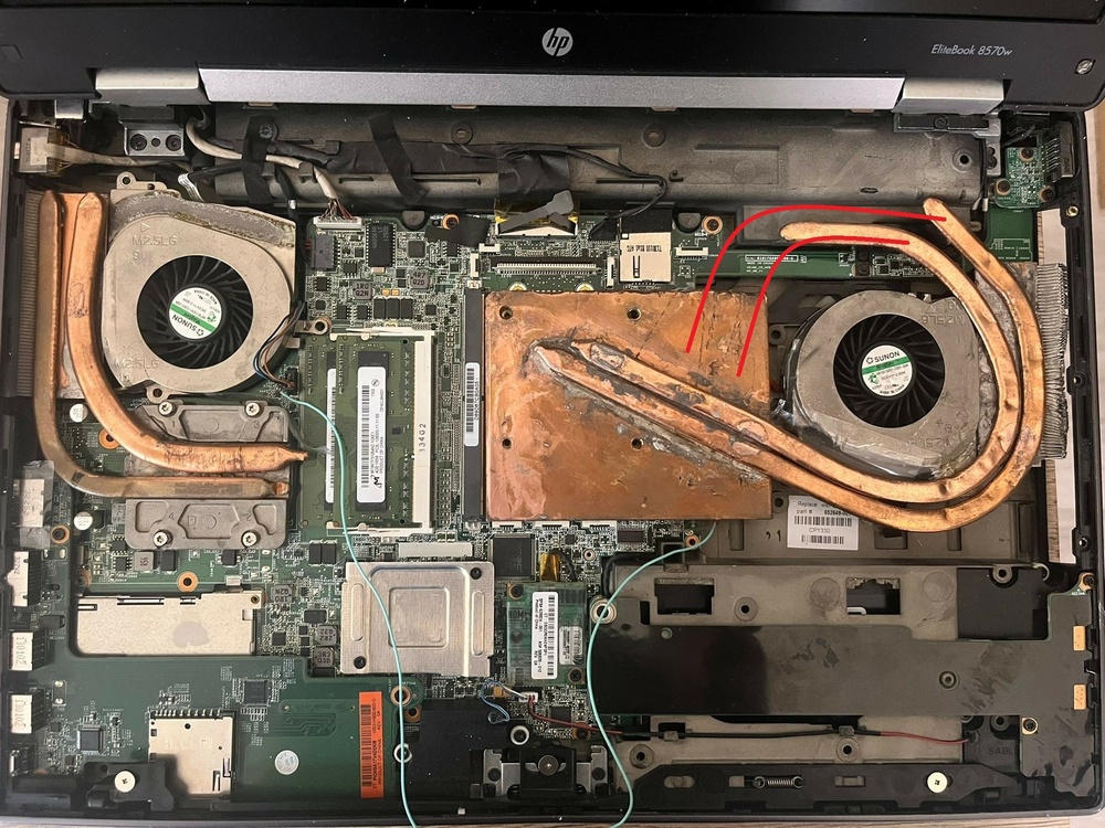
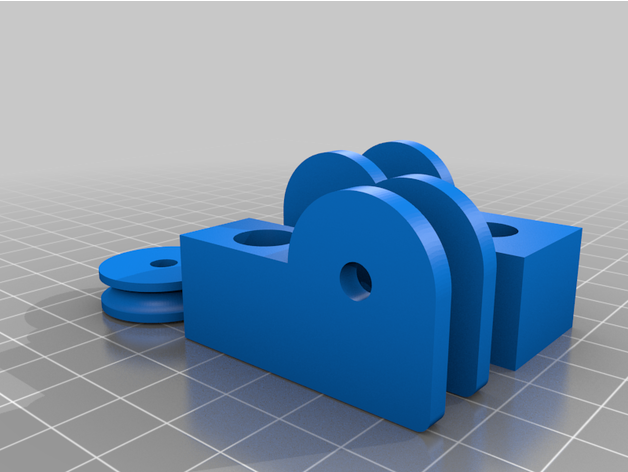
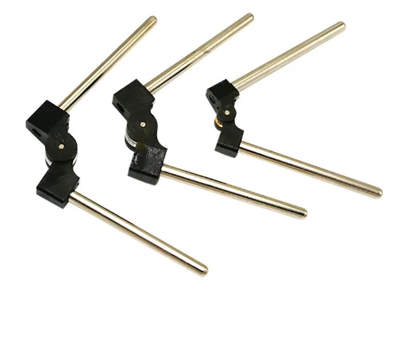
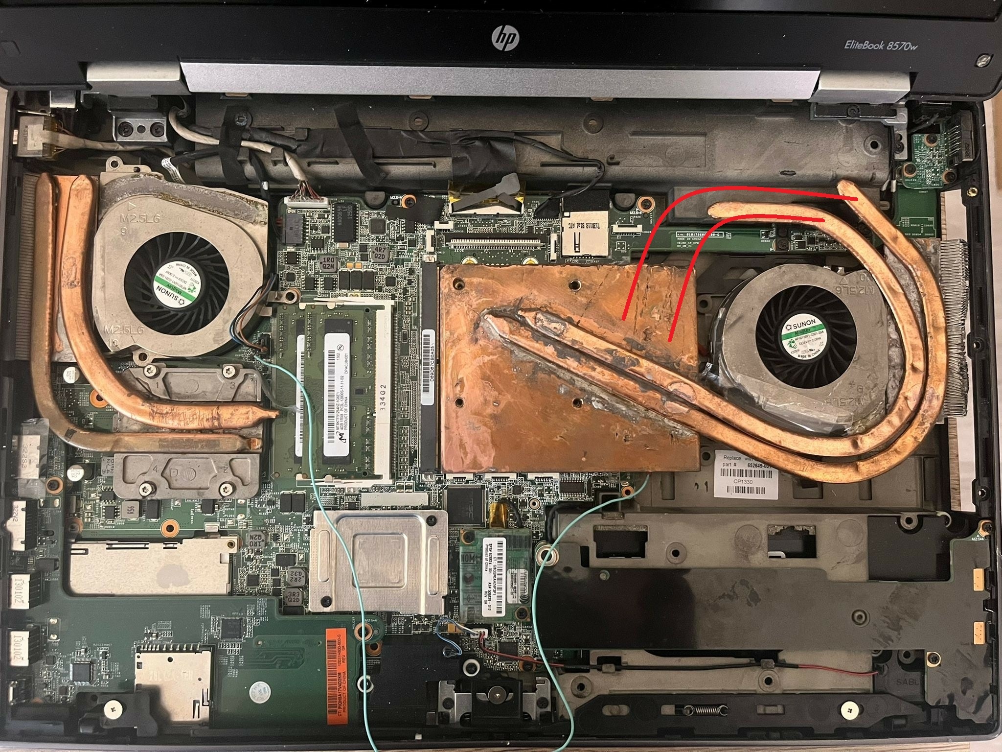
Hi The very best thing you can do in this case is to close the loop by soldering on shorter heat pipes. As a next step, you could ask someone with a 3D printer to make a simple tube bender, or even buy one and use 5mm heat pipes to bend them as needed and flatten them to the required thickness at the contact (soldering) points. https://www.ebay.co.uk/itm/283251571555 There’s also the option to adjust the fan blades themselves their number and size. The basic idea however is very good. Great work.