
DoenerBoy123
-
Posts
33 -
Joined
-
Last visited


DoenerBoy123's Achievements
")


-
@KnibenJust like you I had immediate shutdowns without any throttling or performance drops, just like if you would cut all power to the device. It always came out of nowhere without any noticeable signs
-

M18x R2 with MSI 970m 6gb, not installing newest drivers.
DoenerBoy123 replied to Signex's topic in Alienware 18 and M18x
Depends on which 1070 you'd like to use. The MSI one needs some cutting at the MXM slot and modifications on the heatsink. With the Zotac GTX 1070 im using you only need to modify the heatsink to make it fit. GPU fan control won't work with the Zotac cards which is why I added a switch to the laptop that forces the GPU fan to run at full speed. The 10xx series GPU don't have any kind of LVDS output, so you need an unlocked bios and have to set the graphics option to SG(switchable graphics) -
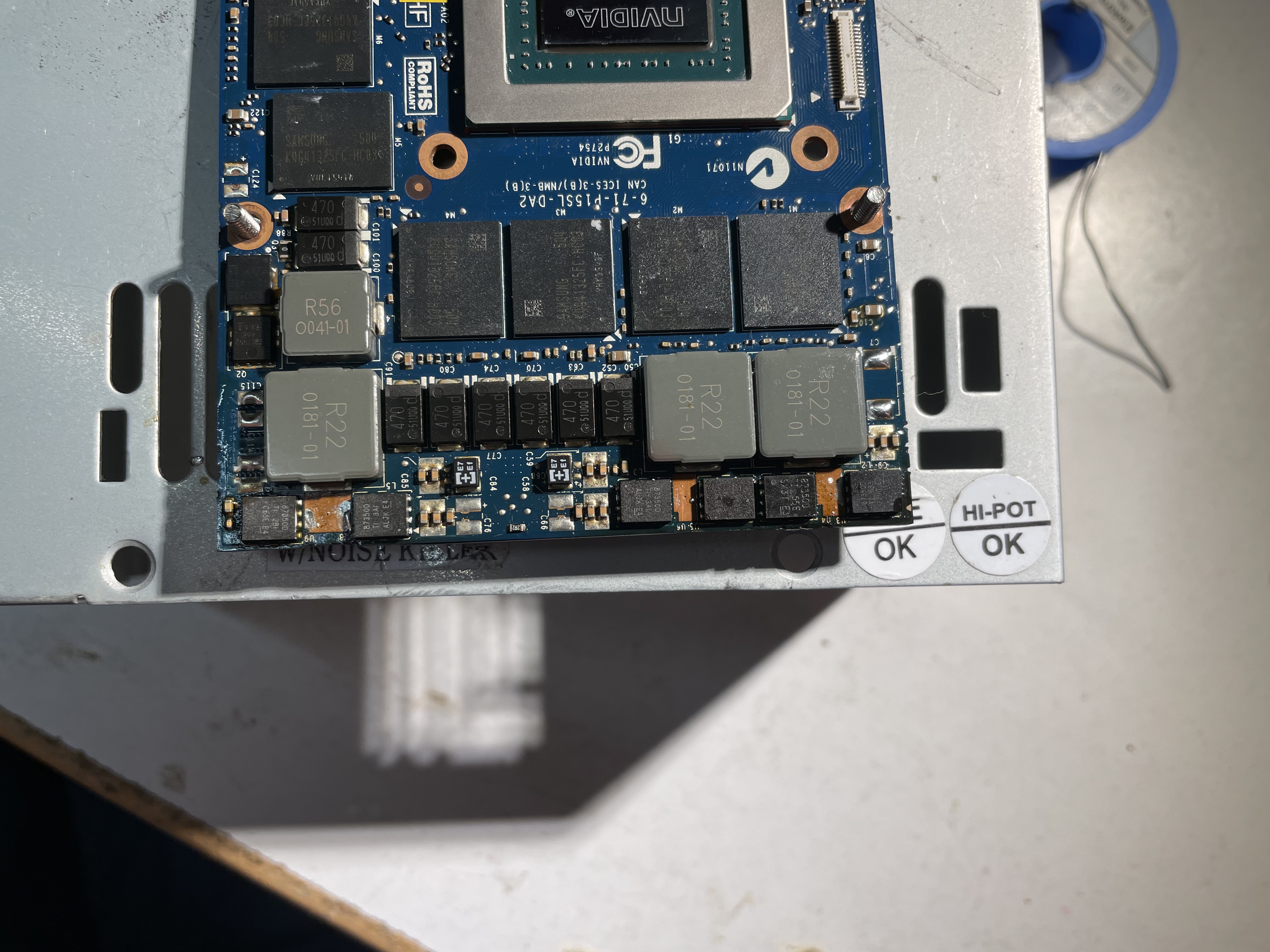
I was actually able to solve the issue. Turns out the thermal pads I’ve been using on the gpu VRMs where not thick enough. Now with the proper size I don’t experience these shutdowns anymore and it runs completely fine unter full load. I also improved the airflow by cutting off the plastic grilles above the fans and at the exhaust. The 9900K I’m using runs at 100W PL1 and 120W PL2 and the 2080 runs at 150W max. I you guys haven’t already, I would give it a try and replace those thermal pads. The chockes don’t necessarily need thermal pads, but make sure the FETs have proper contact, they’re much more important. Same goes for the CPU VRMs. I can test if this behavior occurs when using the stock 330W PSU to rule this out as another cause of this problem
-
I have the same shutdown problem with my P775TM1-G with RTX 2080, 9900K, custom heatsink and the 780W power supply. Installed is the Dsanke bios along EC image of xmg. I’m quite frustrated with this as I’ve never experienced something like that(In such cases it always was the PSU). Would be very nice if someone could help me with this
-
Okay, I was actually way to stupid to use Google. I updated the EC using a premade package ive found on XMG/SAGERs site. For the BIOS I've used the unlocked version from dsanke found on Github and flashed it using the uefishell and afuefi, even tho not recommended. BIOS: https://github.com/supermarsx/other-clevo-modded-bios (0729) EC: https://download.schenker-tech.de/package/xmg-ultra-17-xul17e19/ (NBC)
-
Hello, I just bought an older Clevo P775TM1-G along with a RTX 2080 mxm. Everything works fine exept that i have to use nvcleaninstall to install the drivers which is expected as the bios is from 2018 without turing support. Ive searched everywhere for a newer BIOS/EC version but couldnt find something/links are down(might also possible that I'm stupid) Could someone provide me the necessary files so that I can upgrade the BIOS? An unlocked BIOS would be nice too. Greetings!
-
Alienware 18 Screen Mods? is it possible EDP mod?
DoenerBoy123 replied to TruenoG7's topic in Alienware 18 and M18x
Can you post some picture of the mentioned board you’ve got? I’d really like to the way it’s supposed to be implemented. My way would be to just manually solder the eDP data channels and smBus lines directly to the MXM slot on the PCB. Another way might be to use the dell wireless display port next to the WiFi card(that weird long mPCIe port). The extra pins are for the video signal which is just eDP/HDMI. These signals do either come from the MXM slot or the PCH and are switched Via MUX. This might be the easiest entry point as you could just design a breakout board for the signals. Does anyone know if there are bios or EC limitations that would prevent this to work? -
Alienware 18 Screen Mods? is it possible EDP mod?
DoenerBoy123 replied to TruenoG7's topic in Alienware 18 and M18x
I’m actually planing on doing this along with connecting the dgpu straight to the mDP connector. In theory it should be possible by adding the eDP and smBus lanes to the mxm slot. Thing is, I don’t know if software modifications are necessary for this to work(bios). There’s also the problem that the DP signal is fragile af. Both wires of each lane needs to have the almost exact same length and impedance- 32 replies
-
- 2
-

-

-
- alienware 18 screen mod?
- screen
- (and 8 more)
-
Interesting, thought this wasn't a thing anymore since often cards have different vBios versions for different amounts of memory. Are there any sources for how to place the resistors for specific memory sizes like for a 980M or 1070M(ex. the MSI version)
-
Would be interesting to know what part of the vBios needs to be modded in order to use that amount of memory. Id really like to try something like that on an old GTX 980
-
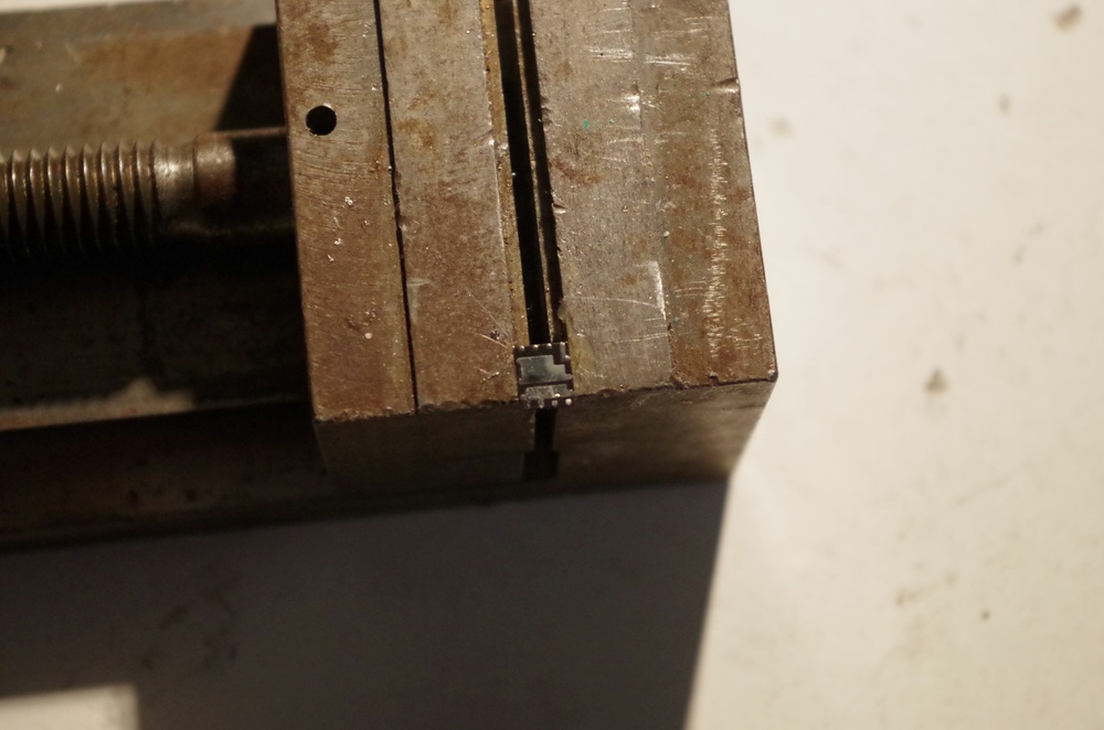
I had the same Issue and also tried that, but this does not seem to fix this(at least in my case). As I mentioned above, you first have to refresh the bios chip with a dump of whatever version. This makes the usb backflash working again which is what your machine brings back to life. I had to desolder the bios chip in order to be recognised by the CH341A programmer, probably because the 3.3V rail draws too much current. My theory is that this Intel HD memory setting bricks the Intel ME portion of the rom which is absolutely necessary for the machine to run. This would explain why the USB backflash method does not work in this case as the ME is responsible for the usb flashing process(as far as I know) @simon h Depending on where you live and if you are willing to, you can sent me your board and I can try to revive it the way it worked for me. Just PM me
-
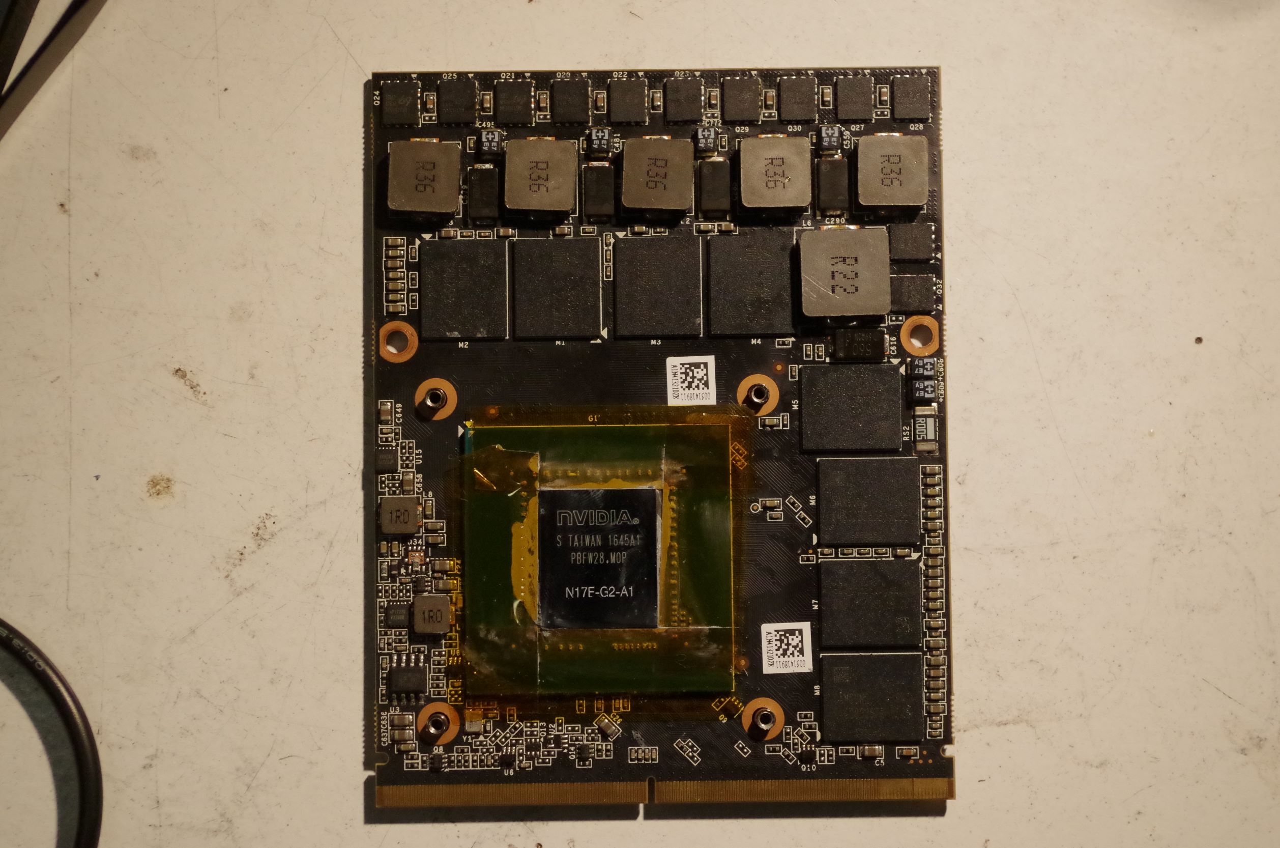
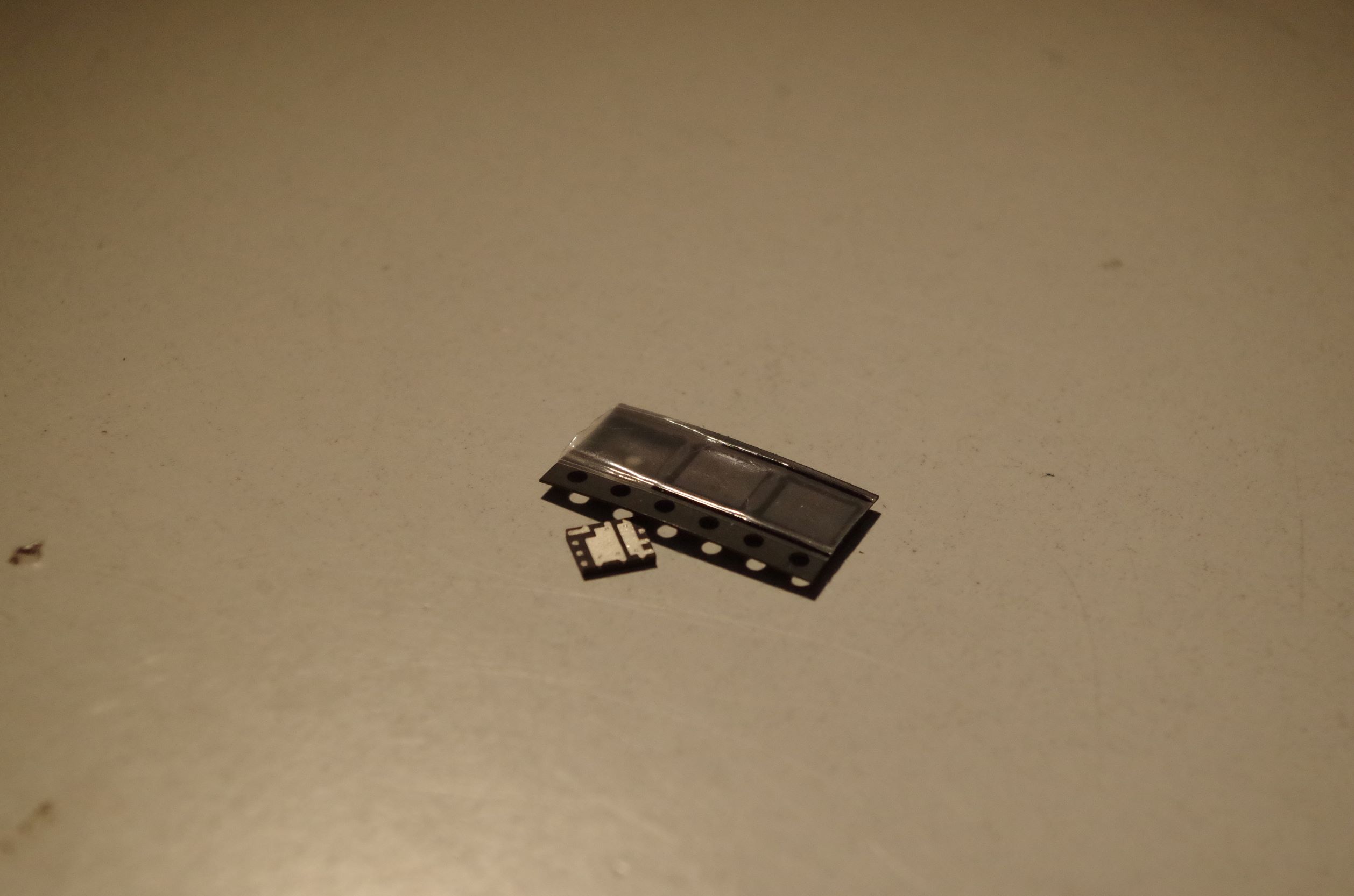
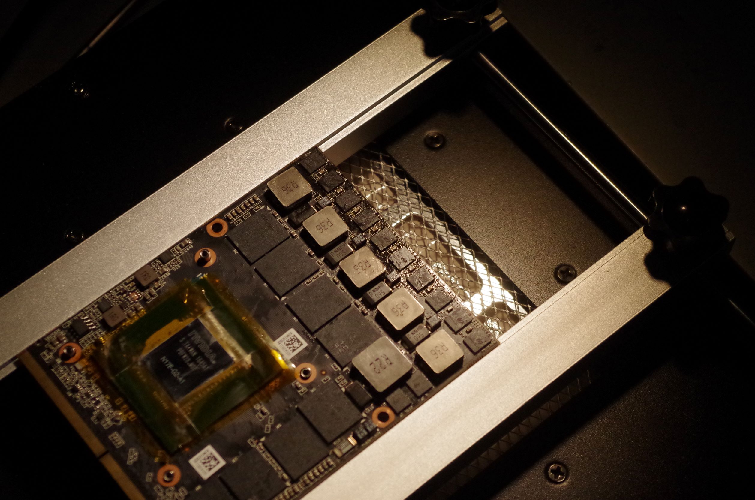
GeForce GTX 980M voltage regulator mod
DoenerBoy123 replied to DoenerBoy123's topic in Components & Upgrades
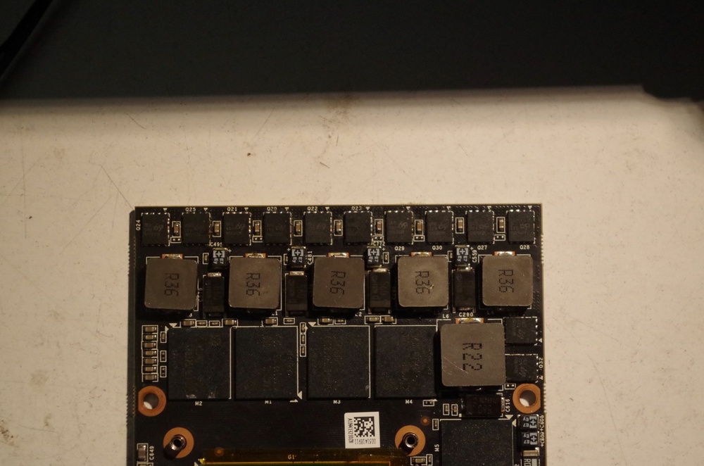
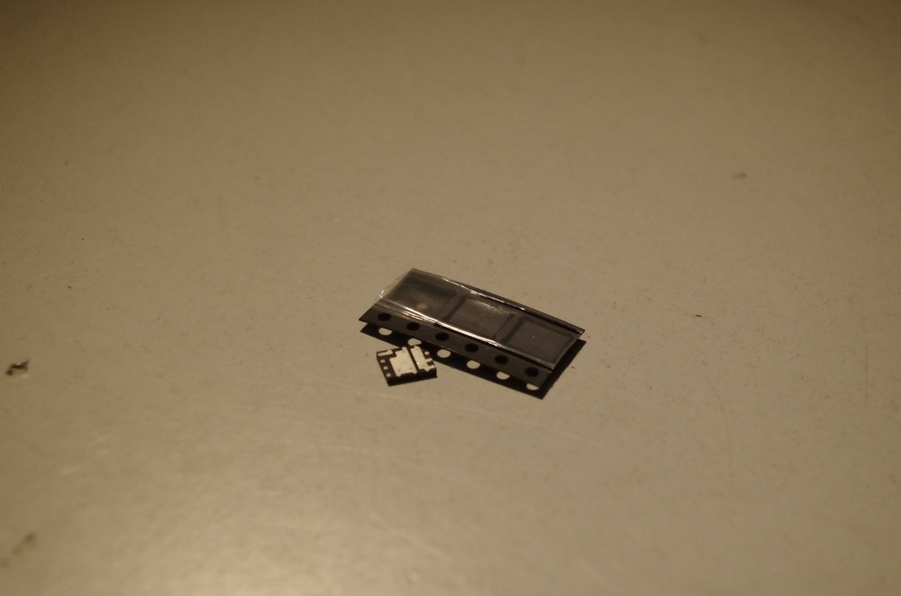
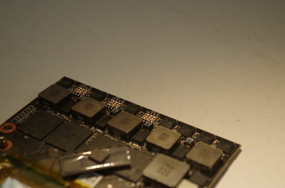
For those who might be interested, I've done something similar to a Zotac GTX 1070, also to increase the available power. There are three unused pads left for a total of 10 MOSFETs. The powerstage for the Vcore circuitry consists out of 5 phases, so at the end you have 2 MOSFETs per phase. The stock config has two phases with 2 MOSFETs and three with 1 MOSFET per phase. I already saw a few cards that had these single MOSFET phases burned up, which is another reason why I did this. All these mods were made on a PCB preheater and with leaded solder to decrease stress on involved components. After that I flashed the vBios from the MSI GT72 to raise the powerlimit from 90W to 115-120W I hope that my text is not too confusing, I'm quite tired ....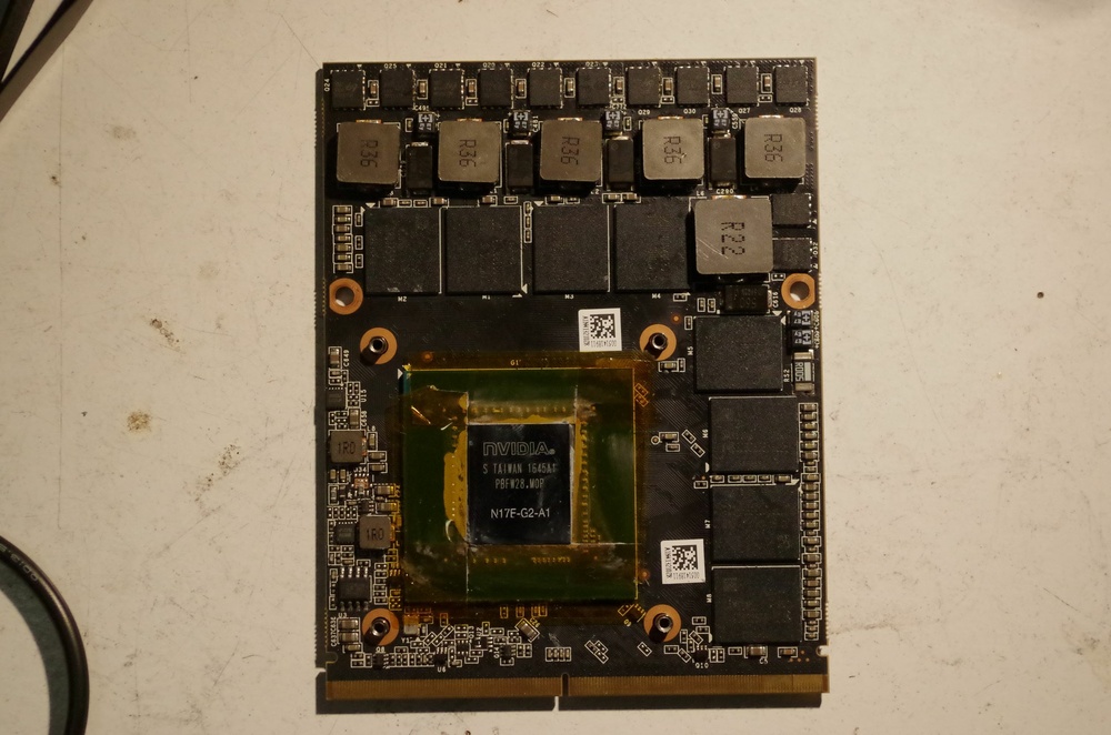


-
M18x R2 - Display overclocking using Custom Resolution Utility
DoenerBoy123 replied to GMP's topic in Alienware 18 and M18x
Try Nvcleaninstall. In my opinion this is a little bit easier and you have more control over the driver intsallation like telemetry and stuff like that -
GeForce GTX 980M voltage regulator mod
DoenerBoy123 replied to DoenerBoy123's topic in Components & Upgrades
This thread is a little bit old now but I want to to give an update about this mod. It’s already a few months past since I’ve mod this card and so far the results are pretty good. I’ve took the mosfets off of an old half working quadro and a 680m I’ve had laying around. The soldering itself was not a big deal, but requires some experience. The maximum power draw with the prema vbios seems to be around 170 watts. The test was done with furmark for a very short time to see how much this card can pull(this was with a 200mhz oc on the core, voltage untouched). In most games the power consumption goes up to around 140-150 watts max with the temperature settling at 65-70 degrees(M17x R4)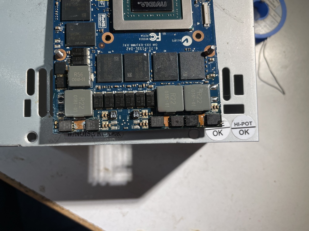
-
Alienware 18 Viking modded drivers for 1060
DoenerBoy123 replied to Yarema's topic in Alienware 18 and M18x
I can recommend NVCleaninstall. In my opinion, this is easier than modding the driver manually and this gives you more control about telemetry and other stuff.