JadeRover
-
Posts
141 -
Joined
-
Last visited
-
Days Won
2
Content Type
Profiles
Forums
Events
Everything posted by JadeRover
-

[6820hq Skylake] Precision 7720 extreme mods
JadeRover replied to JadeRover's topic in Components & Upgrades
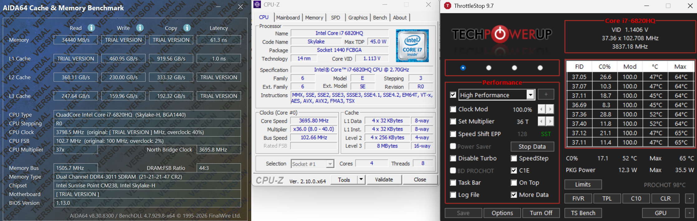
Hello, so a bit of an update I got 2x8gb of 3200Mhz ram at a good price, using smockeless UMAF I first booted into the "Advanced" bios with some 2666Mhz ram and limited Ram speed to 2933Mhz. If I booted directly with my 3200Mhz sticks, since the machine goes for the highest speed you ram can achieve, it will not boot at 3200Mhz and gives a ram error code. Doing this method allows me to then swap the 2666Mhz ram for my 2x8gb of 3200Mhz ram and here are the results with a 102.7Mhz BCLK ! That's right, thanks to BCLK overclocking my ram is now running at 3011Mhz ! 3Ghz barrier passed ! Also for skyake the PCIe and BCLK clocks are seperate, I went over the documentation again and that is why you can get high BCLK value without causing problems for the rest of the system (only ram and cpu get a clock boost). I still need to find a way to get more than 102.7Mhz that is limited by intel ME version. I know it is possible as in this review of the MSI GT83vr with 6920HQ cpu, they achieved close to 105Mhz bclk : Overclocking sur le PC portable MSI GT83VR 6RF-037FR (SLI GTX 1080 / Core i7-6920HQ) Zoom of the picture :
-
Hello, how is your project doing ? I am curious, did you isntall the xeon motherboard ? If so can you get throttlestop and check if the cpu has some overclocking bins ? I am curious if xeons have them as I am currently hesitating between getting a xeon motherboard or a 7920hq motherboard that I know for a fact has +6 turbo overclocking bins. Thanks.
-
HP Elitebook 8570W - is it still good ? Hardware modifications
JadeRover replied to GuitarG's topic in Custom Builds
Ouch, that's unfortunate, maybe the age of the liquid cristals is making the image burn in ? I did notice that the DC screen on my m6700 would get very hot at the bottom of the screen bezel, where the eDP to LVDS converter sits, like 60°C hot ! -
HP Elitebook 8570W - is it still good ? Hardware modifications
JadeRover replied to GuitarG's topic in Custom Builds
Hello, Yes, keep in mind all green pcb M3000m are the same regardless of HP or DELL branding, the only reason they call some DELL and others HP is for the different vbios. So yes if you convince the seller to flash that vBIOS for you it will work. Regarding driver install, you will need to mod an official driver yourself with nvflash (not complicated there are plenty of short tutorials on how to do so). No whitelist has never been an issue for me, only MXM laptops that have a whitelist and that I know of are lenovo P70 and P71 as well as early clevo dual MXM gpus laptops. Haha ok, honestly I would get a CH341a programmer, it really isn't that difficult to get it working, you can then flash 84.04.9B.00.14, especially if you still have your m3000m card with a zbook 17 g3 compatible vbios. -
HP Elitebook 8570W - is it still good ? Hardware modifications
JadeRover replied to GuitarG's topic in Custom Builds
Hello, Yes luckily M3000m is getting really cheap, I got mine for 70 euros last year, now the price has dropped ! Probably the best price to performance card you can get for a working MXM card with little hassle (it also has LVDS support for even older MXM laptops). I would get the "for DELL" version. I had gotten mine from aliexpress for my precision m6700 that also has eDP on DP_D (just like your system) it was branded "for DELL" as well and it did have the correct display outputs set in the vbios. It was plug and play and my internal LCD worked properly, I didn't check the display port but I assume it works as well. - I think "for HP" is for the zbook 17 g3 that these cards originally came from where you have eDP on DP_C -> You would have the problem you had previously of diplay output mismatch. - I think "for DELL" is for dell precision 7710 that these cards where shipped in as well. That laptop has eDP on DP_D -> Would fix your problem. Good luck ! You can always sell your old card for probably the same price you got it for on ebay. -
HP Elitebook 8570W - is it still good ? Hardware modifications
JadeRover replied to GuitarG's topic in Custom Builds
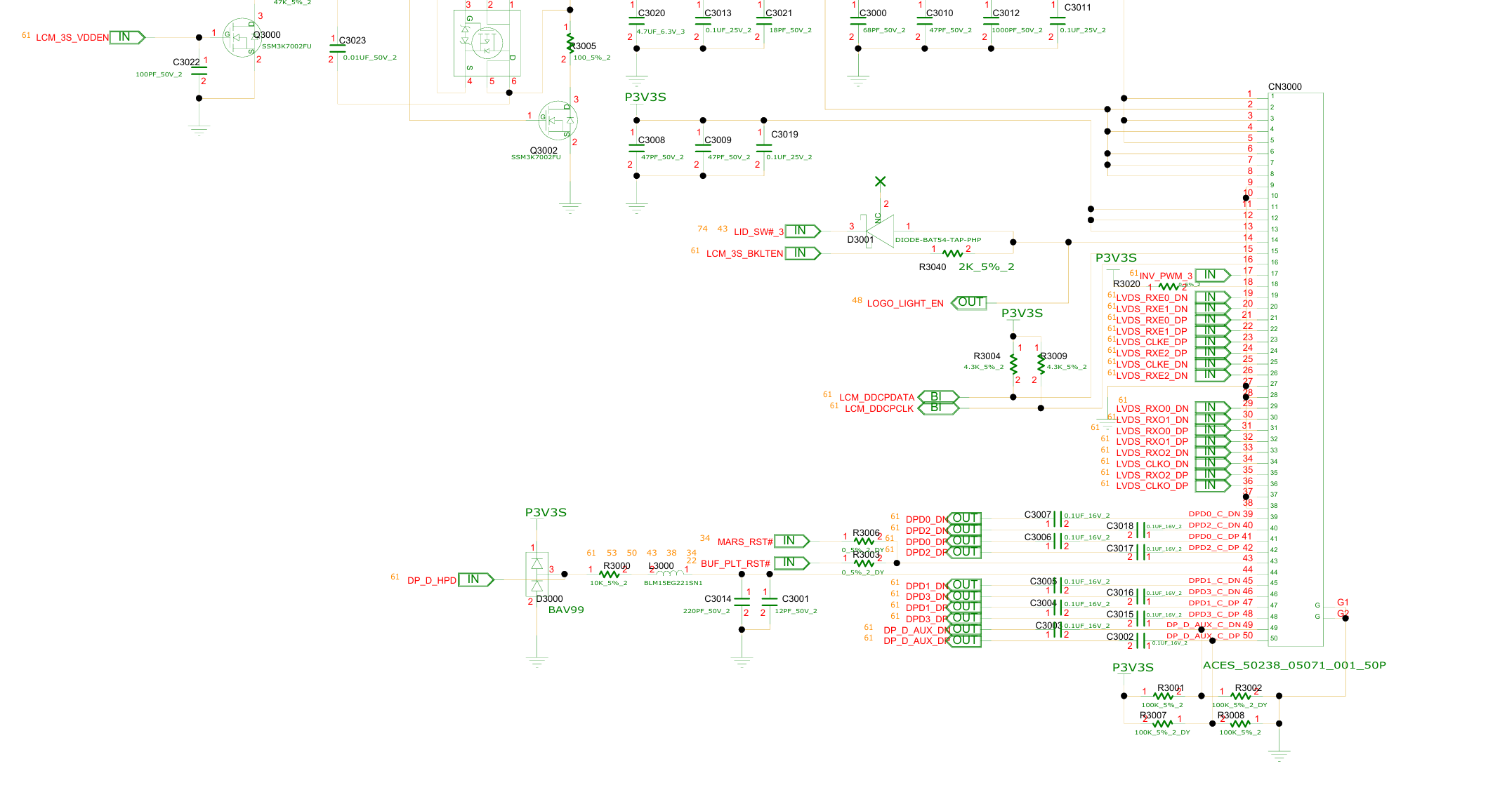
Hello, yes I think I know what the problem is. You 8770W with dreamcolor screen connects directly to the GPU in the MXM slot meaning that the GPU must be configured to have eDP output to the dreamcolor screen (dreamcolor LCD uses LVDS but all laptops from that era with DC screen use an internal eDP to LVDS converter -> GPU needs eDP output to be set on the correct lane for it to work) Your 8770w had eDP on lane "D" of the MXM slot *, the signal then goes to the LCD connector, then to the eDP to LVDS converter and finally to the LVDS DC screen. See schematic of your 8770w, eDP are on the last 10 pins of the LCD connector, signal are named DPDx_Dx = DP_D The issue is that the zbook 17 g3 you got the card from uses eDP on lane "C" ! So the card is configured to output eDP on the wrong channel compared to your 8770w = no display. (I know this from my first hand experience getting MXM cards to work on my 17 g3 and getting no display as well because of eDP lane mismatch) The fix is simple, you need to flash a vbios that has the correct display configuration to the card. This dell vbios has eDP on DP_D (as it is from a precision 7710 that has eDP on DP_D): https://www.techpowerup.com/vgabios/221521/221521 They are several ways to flash the correct vbios. I recommend getting a CH341a programmer with 1.8v adapter, it costs 10 dollars max. Good luck and ask away if you have more questions * This is good news as this is the standard for MXM gpus, you could even upgrade to an RTX card by x-vision or other brands that come only with a vbios configured with eDP on DP_D !
-
[WIP] Nvidia-vBIOS-Clock-Power-Tweaker
JadeRover replied to JadeRover's topic in Components & Upgrades
BTW what does gpu z show? Because it communicates with the Nvidia driver to get the clock values. Maybe I messed up (again) and have the wrong algorithm to read/write clocks. It would be nice to see if gpu z shows my custom clocks ore the clocks you are seeing in benchmark. Thanks. -
[WIP] Nvidia-vBIOS-Clock-Power-Tweaker
JadeRover replied to JadeRover's topic in Components & Upgrades
OK that is unfortunate. No clue why memory clocks work on p106m but not on p6 as the actual hex values are the same. Same thing for the core clocks on p6. Maybe 2000mhz is too high, we can try 1800 mhz next. Also you can try a custom vbios made with v1.1 on p3200 and p4200 as clock values should now be saved correctly. -
[WIP] Nvidia-vBIOS-Clock-Power-Tweaker
JadeRover replied to JadeRover's topic in Components & Upgrades
Here is an updated version (core clocks are in the correct format). Set to 2000Mhz (again vrel limit before seing this value) You said the memory was good, it boosted to 2000/4000Mhz ? Because checking again my custom memory clock was not in the expected format, strange that it still worked. I change the memory clock in this _1 version. It is in the expected format in version _1. In version _2 it is in the same format as my last p106m vbios. if you can give both a try that would be good. p106m_OC_checked_1.bin p106m_OC_checked_2.bin -
[WIP] Nvidia-vBIOS-Clock-Power-Tweaker
JadeRover replied to JadeRover's topic in Components & Upgrades
Interesting. I might add these IDs but as a read only to see what card is recognized, especially for P6 and other cards that have a non standard clock layout and need different calculations in order to display the correct values. -
[WIP] Nvidia-vBIOS-Clock-Power-Tweaker
JadeRover replied to JadeRover's topic in Components & Upgrades
It should normally. I haven't tested it. When you say 8 bit checksum, you mean the header checksum ? Or the last 8 bits of the 32bit body checksum ? -
[WIP] Nvidia-vBIOS-Clock-Power-Tweaker
JadeRover replied to JadeRover's topic in Components & Upgrades
Yep, base clock is now 1230Mhz and boost is now 2000Mhz (you will hit vrel limit before seing this value) Memory is now at 4000Mhz target power is 100w, limit power is 120w and power slider is enabled. Checksum was fixed as well. You can try this @ssj92 teslap6_OC_power_mod.rom -
[WIP] Nvidia-vBIOS-Clock-Power-Tweaker
JadeRover replied to JadeRover's topic in Components & Upgrades
New version : Release v1.1 | Nvidia-vBIOS-Clock-Power-Tweaker · JadeRover/Nvidia-vBIOS-Clock-Power-Tweaker This one should correctly save the clock values, you can give it a try @ssj92. I made sure it would work for the p3200 and p4200, I tested some roms on techpowerup. (clocks are in the correct 2x2 byte format). -
[WIP] Nvidia-vBIOS-Clock-Power-Tweaker
JadeRover replied to JadeRover's topic in Components & Upgrades
What does the GPU-Z windows show ? -
[WIP] Nvidia-vBIOS-Clock-Power-Tweaker
JadeRover replied to JadeRover's topic in Components & Upgrades
Ok, because the v1.0 will not work i made a mistake for the clock calculations -
[WIP] Nvidia-vBIOS-Clock-Power-Tweaker
JadeRover replied to JadeRover's topic in Components & Upgrades
Ok, only using the power bios ? -
[WIP] Nvidia-vBIOS-Clock-Power-Tweaker
JadeRover replied to JadeRover's topic in Components & Upgrades
Yes, there is a certification issue, might be possible to bypass using OMGvflash by veil for turing cards, any newer cards will not work unfortunately. Pascal works. Even with a hardware flasher it will not work, card will refuse to boot and show error 43. -
[WIP] Nvidia-vBIOS-Clock-Power-Tweaker
JadeRover replied to JadeRover's topic in Components & Upgrades
Ok, I really don't have high hopes for the clock values as I got them by dividing the 4 bytes of hex by 32768. As it turns out you have to substract 16384 and then multiply by 2... on each 2 byte chunk of the 4 byte clock value ! See here : https://rog-forum.asus.com/t5/rog-gaming-notebooks/laptop-pascal-vbios-unlocks-quot-wip-quot/td-p/658321 I'll make a version only with power editing that way you can test that out (as it should work fingers crossed), while I fix the clock editing. Here is this [POWER ONLY] version 1.0 : Release v1.0 | [POWER ONLY] Nvidia-vBIOS-Clock-Power-Tweaker · JadeRover/Nvidia-vBIOS-Clock-Power-Tweaker -
[WIP] Nvidia-vBIOS-Clock-Power-Tweaker
JadeRover replied to JadeRover's topic in Components & Upgrades
Also very important, version 1.0 of my program might be saving the wrong clock values !! I will be making some actual vbios tests on my p3000 in my m6700 this week end. In the meantine no one should try to flash a custom vbios made from my program. -
[WIP] Nvidia-vBIOS-Clock-Power-Tweaker
JadeRover replied to JadeRover's topic in Components & Upgrades
Hello, this is P106m card vbios ? Manual looking at the clock table, it has only one core value of 1290Mhz and all the others are null (FF). For the memory clock it is 1500Mhz (in afterburner clock dual rank mode). Also the power table is a desktop type with 3 values (not supported by my program). Those I read from your vbios are all at 100w. I can make you a custom vbios to try if you want. I made one quickly, boost to 1910Mhz (I changed all the instances of 1290Mhz to 1910Mhz) and mem up to 2000 Mhz you can give it a try, the checksum was fixed as well. You will probably hit a vrel limit and be around the 1850Mhz mark p106m_vbios_checked.rom -
[WIP] Nvidia-vBIOS-Clock-Power-Tweaker
JadeRover replied to JadeRover's topic in Components & Upgrades
I don't have an ETA. This is a side project I have my active life to attend to. DP_B is probably DP++ so it can output either DP or HDMi or even DP+HDMi thanks to a demuxer switch on the laptop (splits the DP++ into one DP and one HDMi). -
[WIP] Nvidia-vBIOS-Clock-Power-Tweaker
JadeRover replied to JadeRover's topic in Components & Upgrades
That's right, fixing one byte and then fixing checksum causes error 43. However I know that upddating the GOP driver found inside the vbios doesn't brick the card : GOP Update and Extraction Tool (Turing) - BIOS/UEFI Modding / BIOS Modding/Flashing Tools - Win-Raid Forum I've tested the utility and it changes the 32 bit checksum but not the 8 bit value of the checksum (modulo 256 checksum is the same). -
[WIP] Nvidia-vBIOS-Clock-Power-Tweaker
JadeRover replied to JadeRover's topic in Components & Upgrades
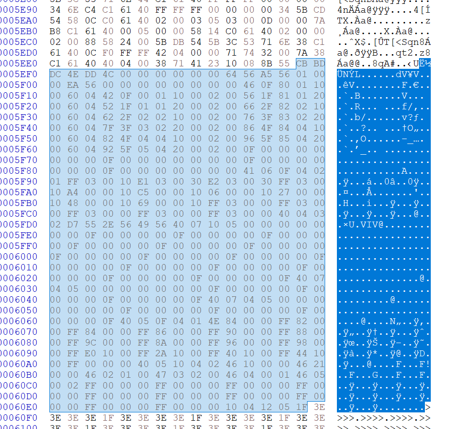
Yes, the display table has tons of info here is a snippet (non parsed data): Highlighted is the entire display table, notice this repeating pattern of 6 lines lines 5F10 and 5F60 starting with header "60". These are the DP_X display entries from A to F
-
[WIP] Nvidia-vBIOS-Clock-Power-Tweaker
JadeRover replied to JadeRover's topic in Components & Upgrades
Version 1.0 is released : Release v1.0 | Nvidia-vBIOS-Clock-Power-Tweaker · JadeRover/Nvidia-vBIOS-Clock-Power-Tweaker Editing and saving vbios is possible + checksum is fixed. Therefore I need volunteers with an external flasher to test on pascal cards these modifications ! -
[WIP] Nvidia-vBIOS-Clock-Power-Tweaker
JadeRover replied to JadeRover's topic in Components & Upgrades
Hello, yes there is a way to do so. The mac rumor vbios have different output table from stock vbios + documentation exists on the "DCB" table (display table) of nvidia vbios, that's the next step of the program is to read and edit these outputs. Unfortunately when testing with an RTX3000 gpu, my custom vbios did not work, the card would be bricked with error 43. Moreover, changing 2 adjacent bytes in the bios by doing +1 and -1 to the hex value (so that checksum is the same) results in a brick as well for this Turing card = meaning that Turing has more security checks then Pascal and any custom vbios bricks the card (also this was documented on mac rumors). AKA turing custom vbios won't be possible 😞